
A video surveillance system and method for smart communities

A video surveillance system and video surveillance technology, applied in closed-circuit television systems, TV system components, stereo systems, etc., can solve problems that cannot be found in abnormal situations and emergency management, difficult to effectively meet actual use, and detect the impact of video signal quality, etc. To achieve the effect of convenient system composition and maintenance, improved convenience, and strong data processing capabilities

Active Publication Date: 2021-04-13
江苏云发智能科技有限公司
View PDF5 Cites 0 Cited by
  • Summary
  • Abstract
  • Description
  • Claims
  • Application Information

AI Technical Summary

Problems solved by technology

[0002] The video surveillance system is an important equipment in the daily management and security management of the current community, and it is used in a huge amount. However, in actual work, it is found that the video surveillance systems used in the current community are often based on traditional camera equipment to monitor specific areas. To meet the needs of use, although it can meet the needs of use to a certain extent, on the one hand, the camera equipment in monitoring is easily disturbed by natural environmental factors, which greatly affects the quality of the detected video signal, and it is difficult to effectively meet the needs of actual use; On the one hand, the traditional video surveillance system often lacks the ability to distinguish and identify the target, or the ability to distinguish and identify is relatively poor. At the same time, it is also unable to analyze, record and evaluate the behavior and habits of the specific target, so that it cannot detect abnormal situations in the community. Timely discovery and emergency management are difficult to effectively meet the needs of actual use

Method used


Image

  • A video surveillance system and method for smart communities
  • A video surveillance system and method for smart communities
  • A video surveillance system and method for smart communities

Examples


Embodiment Construction

[0025] In order to make the technical means, creative features, goals and effects achieved by the present invention easy to understand, the present invention will be further described below in conjunction with specific embodiments.

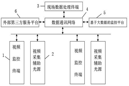
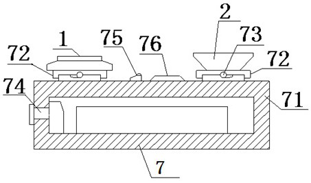
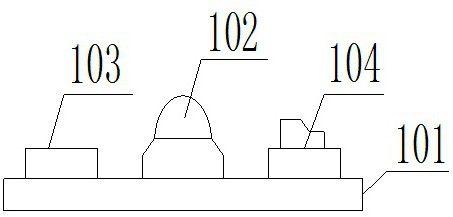
[0026] Such as Figure 1-5 As shown, a video monitoring system for a smart community includes a video monitoring terminal 1, a video acquisition auxiliary light source 2, an on-site data processing terminal 3, a data communication network 4 and a monitoring platform 5 based on big data, a video monitoring terminal 1, There are several video acquisition auxiliary light sources 2, and a video monitoring terminal 1 and at least one video acquisition auxiliary light source 2 form a working group, there are several working groups, and each working group is electrically connected to at least one on-site data processing terminal 3, and on-site data processing The terminal 3 also establishes a data link with the monitoring platform 5 based on big data thr...


PUM


Abstract

The invention relates to a video monitoring system and method for smart communities, including a video monitoring terminal, a video acquisition auxiliary light source, an on-site data processing terminal, a data communication network and a monitoring platform based on big data, a video monitoring terminal, a video acquisition auxiliary There are several light sources, and a video monitoring terminal and at least one video acquisition auxiliary light source form a working group, and the on-site data processing terminals are electrically connected between the working groups, and the on-site data processing terminals are established through the data communication network and the monitoring platform based on big data. Data link, and also electrically connected with the external power supply circuit. Its use method includes three steps: system networking, monitoring operation and data analysis. The invention can accurately realize the efficient recognition and recognition of the target object, and can predict and analyze the behavior state of the target object.

Description

technical field [0001] The invention relates to a video monitoring system and method for a smart community, belonging to the technical field of video signal processing and data communication. Background technique [0002] The video surveillance system is an important equipment in the daily management and security management of the current community, and it is used in a huge amount. However, in actual work, it is found that the video surveillance systems used in the current community are often based on traditional camera equipment to monitor specific areas. To meet the needs of use, although it can meet the needs of use to a certain extent, on the one hand, the camera equipment in monitoring is easily disturbed by natural environmental factors, which greatly affects the quality of the detected video signal, and it is difficult to effectively meet the needs of actual use; On the one hand, the traditional video surveillance system often lacks the ability to distinguish and iden...

Claims


Application Information

Patent Timeline
Patent Type & Authority Patents(China)
IPC IPC(8): G06K9/00G06N3/04G03B15/02H04N5/33H04N7/18H04N13/204
CPCG06N3/049H04N7/181H04N5/33H04N13/204G03B15/02G06V20/42G06N3/044G06N3/045
Inventor 韩桂海
Owner 江苏云发智能科技有限公司
Learn More