Supercharge Your Innovation With Domain-Expert AI Agents!

A camera control system and method based on piezoelectric ceramics

A piezoelectric ceramic and control system technology, which is applied in the parts of TV systems, parts of color TVs, TVs, etc., can solve the problems of unclear shooting pictures, asynchronous shooting and focusing, etc.

Active Publication Date: 2022-07-05
SKYVERSE TECH CO LTD
View PDF10 Cites 0 Cited by
  • Summary
  • Abstract
  • Description
  • Claims
  • Application Information

AI Technical Summary

Problems solved by technology

[0004] In order to solve the problem that the control method of the high-speed industrial camera in the above-mentioned traditional technology has asynchronous shooting and focusing, and then makes the shooting picture collected by the camera unclear, the application specially provides a piezoelectric ceramic-based camera that can improve the definition. camera control system

Method used


Image

  • A camera control system and method based on piezoelectric ceramics
  • A camera control system and method based on piezoelectric ceramics
  • A camera control system and method based on piezoelectric ceramics

Examples


Embodiment 1

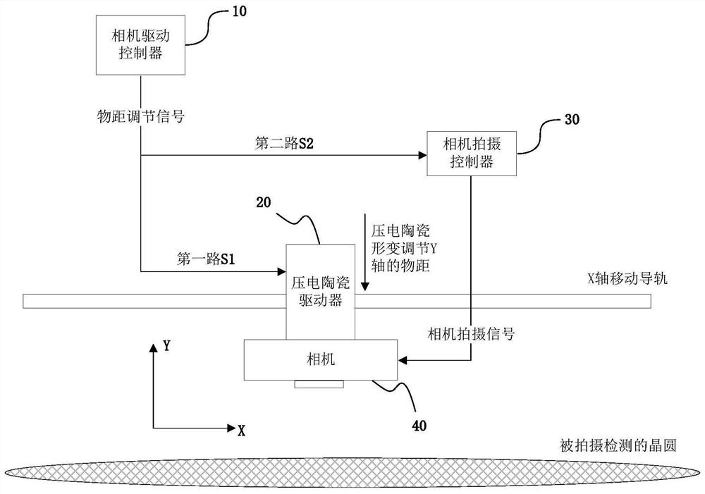
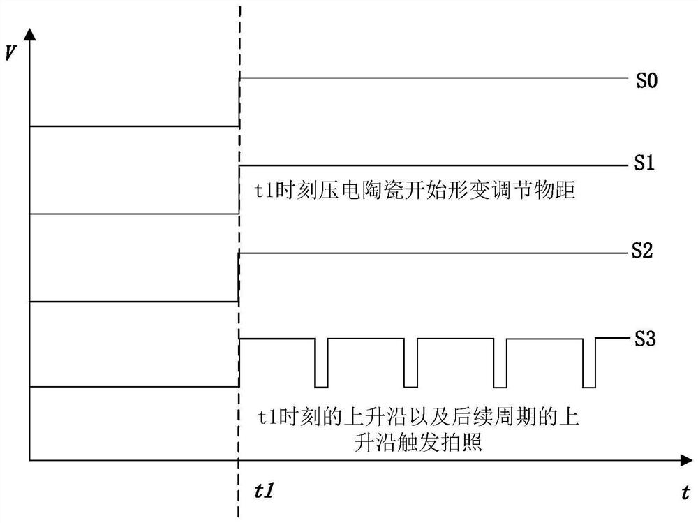
[0052] In this embodiment, the camera shooting controller 30 is configured to generate the camera shooting signal S3 when the rising edge of the second channel signal S2 is detected.

[0053] That is to say, the second signal S2 can be used as a switch signal or a trigger signal of the camera shooting controller 30 to transmit the camera shooting signal S3 to the camera. refer to image 3 As shown in the signal sequence, at time t1, the camera drive controller 10 starts to control focusing, and the object distance adjustment signal S0 generates a rising edge. Correspondingly, at time t1, the first signal S1 and the second signal S2 also rise. edge, the camera shooting controller 30 detects the rising edge of the second signal S2, determines that the switch signal transmitting the camera shooting signal S3 to the camera is in a trigger state, and starts to generate the camera shooting signal S3 and transmit it to the camera.

[0054] Further, since the piezoelectric ceramic dr...

Embodiment 2

[0057] In this embodiment, the camera shooting controller 30 includes an encoder and a modulator (or a synthesizer), the encoder is used to generate the original control signal S4, and the modulator is used to modulate the original control signal S4 and the second signal S2 into a camera Capture signal S3.

[0058] That is to say, in this embodiment, the camera shooting controller 30 continuously transmits the camera shooting signal S3 to the camera, the encoder continuously generates the original control signal S4, and the modulator modulates the original control signal S4 to the second signal S2 On the other hand, the continuous camera shooting signal S3 is generated, and since the second signal S2 is only high after the rising edge, the modulated camera shooting signal S3 is only after the rising edge of the second signal S2. A rising edge occurs, allowing the camera to start shooting after the object distance has been adjusted.

[0059] Further, the modulator can be used ...


PUM


Abstract

The present application discloses a piezoelectric ceramic-based camera control system, including a camera driving controller, a piezoelectric ceramic driver, a camera shooting controller, and a camera. The camera driving controller is used to generate an object distance adjustment signal, and the object distance The adjustment signal is divided into a synchronized first signal and a second signal, the first signal is transmitted to the piezoelectric ceramic driver, and the second signal is transmitted to the camera shooting controller; the pressure The electric ceramic driver is used to drive the piezoelectric ceramic to deform according to the first signal, so as to adjust the object distance of the camera; the camera shooting controller is used to generate the camera shooting signal according to the second signal, and the The camera shooting signal is transmitted to the camera; the camera is used for shooting according to the camera shooting signal. In addition, based on the system, a piezoelectric ceramic-based camera control method is provided, and the system and method can improve the sharpness of camera shooting.

Description

technical field [0001] The present application relates to the technical field of industrial control, and in particular to a camera control system and method based on piezoelectric ceramics. Background technique [0002] In traditional technology, high-speed industrial cameras are required for defect inspection of wafers. The topography of the inspected wafer can be photographed by a high-speed industrial camera, and then the features of the obtained topography of the wafer can be analyzed to determine whether there are defects. [0003] The control of the high-speed industrial camera in the traditional technology consists of two parts. The first part is to drive the high-speed industrial camera to move by controlling the deformation of the piezoelectric ceramic to adjust the distance (object distance) between the high-speed industrial camera and the wafer to be inspected, so that the The industrial camera performs automatic focusing, and the other part is to control the hig...

Claims


Application Information

Patent Timeline
Patent Type & Authority Patents(China)
IPC IPC(8): H04N5/232H01L21/67
CPCH01L21/67288H01L21/67294H04N23/67
Inventor 陈鲁郭亚英马砚忠张嵩
Owner SKYVERSE TECH CO LTD
Features
  • R&D
  • Intellectual Property
  • Life Sciences
  • Materials
  • Tech Scout
  • Unparalleled Data Quality
  • Higher Quality Content
  • 60% Fewer Hallucinations
Learn More