Pore plate edge grinding device
An edge and orifice plate technology, which is applied to machine tools, grinding drives, and grinders suitable for grinding the edge of workpieces, can solve the problems of complex operation, low efficiency, time-consuming and labor-intensive, and achieves time-saving and labor-saving operation and simple operation. Effect
- Summary
- Abstract
- Description
- Claims
- Application Information
AI Technical Summary
Problems solved by technology
Method used
Image

Examples
Embodiment 1
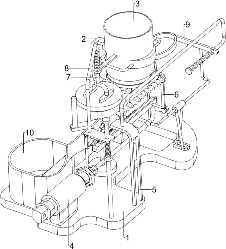
[0073] A device for grinding the edge of orifice plate, such as figure 1 , image 3 and Figure 5 As shown, it includes a bottom plate 1, a first support frame 2, a discharge box 3 and a grinding mechanism 4, a first support frame 2 is provided on the left side of the upper rear side of the bottom plate 1, and a discharge box is provided on the inner side of the upper part of the first support frame 2 3. There is a grinding mechanism 4 on the bottom plate 1, and the grinding mechanism 4 cooperates with the discharge box 3.
[0074] Manual grinding of orifice plates is time-consuming, labor-intensive, inefficient and complicated to operate. This equipment can automatically polish the orifice plates, saving time and effort, high in efficiency and simple in operation. First, people put a stack of orifice plates in the discharge box 3, The lowermost orifice plate falls on the first support frame 2, and people push the lowermost orifice plate in the discharge box 3 forward to the...
Embodiment 2
[0076] On the basis of Example 1, such as figure 2 and Figure 4 As shown, the grinding mechanism 4 includes a second support frame 41, a cylinder 42, a push rod 43, a rack 44, a first round block support 45, a supporting rotating table 46, a gear 47, a grinder 48, a circular plate 48 and a stabilizing bar 49, the upper front side of the base plate 1 is provided with a second support frame 41, the inner side of the second support frame 41 is provided with a cylinder 42, the rear side of the cylinder 42 is provided with a push rod 43, and the rear side of the top of the push rod 43 is provided with a rack 44. Bar 44 right side rear portion is provided with the first round block support 45, and base plate 1 upper middle part is provided with stabilizing bar 49, and stabilizing bar 49 upper inner side rotation type is provided with support rotating table 46, and supporting rotating table 46 cooperates with base plate 1, supports and rotates. The middle part of table 46 is provi...
Embodiment 3
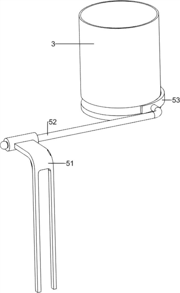
[0079] On the basis of Example 2, such as figure 1 , image 3 , Figure 4 , Figure 5 , Figure 6 and Figure 7 As shown, it also includes a pushing mechanism 5, the bottom plate 1 is provided with a pushing mechanism 5, the pushing mechanism 5 cooperates with the discharge box 3, and the pushing mechanism 5 includes a third support frame 51, a pulling rod 52 and an arc-shaped Frame 53, bottom plate 1 upper front right side is provided with the 3rd bracing frame 51, and the third bracing frame 51 upper side middle part inner sliding type is provided with pull rod 52, and pull rod 52 left side rear part is provided with arc-shaped frame 53, arc Shaped frame 53 cooperates with discharging box 3.
[0080] After people put a stack of orifice plates in the discharge box 3, they manually make the pull rod 52 slide forward in the third support frame 51, thereby driving the arc-shaped frame 53 to move forward, and then the lowermost side of the discharge box 3 is moved forward. ...
PUM
 Abstract
Description
Claims
Application Information
 - R&D
- Intellectual Property
- Life Sciences
- Materials
- Tech Scout
- Unparalleled Data Quality
- Higher Quality Content
- 60% Fewer Hallucinations
Browse by: Latest US Patents, China's latest patents, Technical Efficacy Thesaurus, Application Domain, Technology Topic, Popular Technical Reports.
© 2025 PatSnap. All rights reserved.Legal|Privacy policy|Modern Slavery Act Transparency Statement|Sitemap|About US| Contact US: help@patsnap.com