Hinge pin connector for tower crane

A tower crane and pin shaft technology, applied in the directions of cranes, bolts, etc., can solve the problems of obstructing the transportation and movement of tower cranes, inconvenient transportation of fixed pin connectors, too large and too long pin shafts, etc., so as to solve the problem of installation and disassembly. , The structure is simple and reliable, and the effect of the pin shaft being too long is solved.

Pending Publication Date: 2021-03-02
JIANGLU MACHINERY & ELECTRONICS GROUP
View PDF0 Cites 0 Cited by
  • Summary
  • Abstract
  • Description
  • Claims
  • Application Information

AI Technical Summary

Problems solved by technology

[0003] At present, conventional tower cranes are generally not equipped with a joint or only a fixed welded joint. Without a joint, the pin shaft is too large and too long, and it is difficult to install by manpower. However, the fixed joint is inconvenient to transport or easy to move. In the case of interference, these traditional methods have virtually increased security risks
The pin joint of conventional tower cranes is welded at the lower part of the pin shaft. How long is the pin shaft? The corresponding length of the pin joint is designed. As a result, due to the excessive length of the pin shaft, the joint joint will protrude from many parts of the tower crane. , obstructing the transportation and movement of the tower crane

Method used


Image

  • Hinge pin connector for tower crane
  • Hinge pin connector for tower crane
  • Hinge pin connector for tower crane

Examples


Embodiment 1

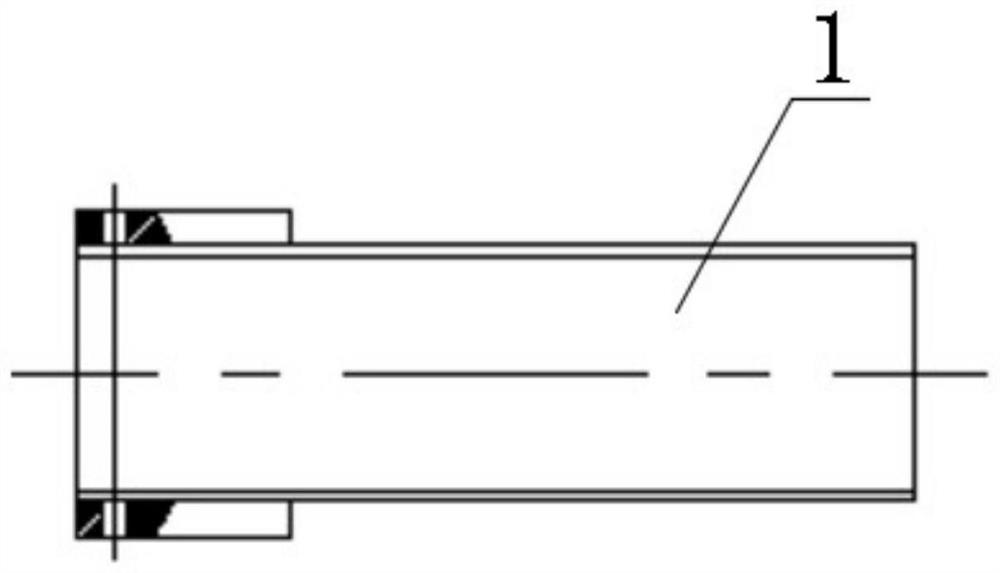
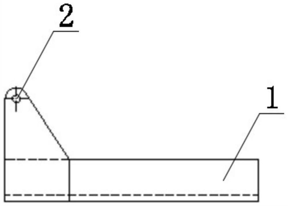
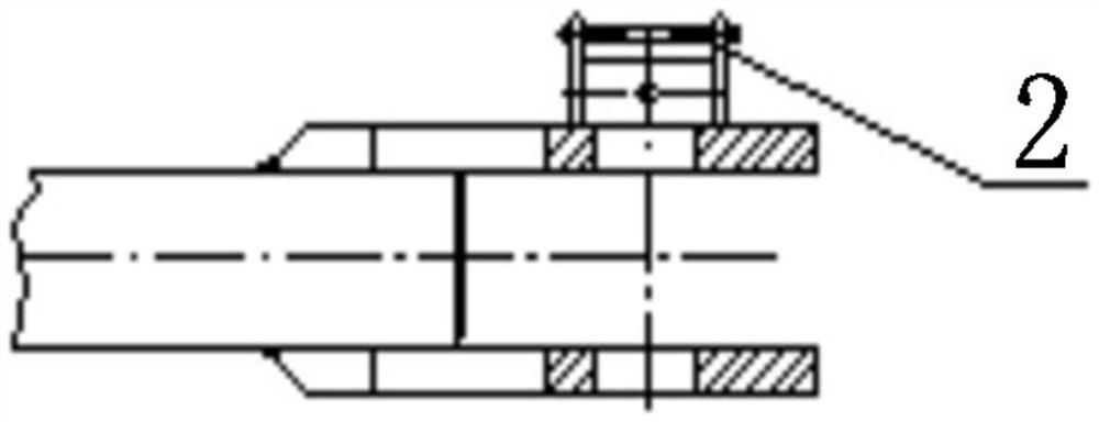
[0027] Such as Figure 1 to Figure 5 As shown, the present invention is a pin connector for a tower crane, comprising a base 1, the base 1 is a cuboid through groove, one end of the base 1 is fixedly connected with a pair of connecting plates 2, and the connecting plates 2 are symmetrically arranged on Both sides of the base 1, the top of the connecting plate 2 is provided with a pin hole, the side of the connecting plate away from the base 1 is fixedly connected with a support plate 3, the support plate 3 is a flat plate, and the other end of the support plate 3 is connected to the Tower crane fixed connection;

[0028] Further, the height of the base 1 is lower than the height of the connecting plate 2;

[0029] Further, the top of the connecting plate 2 is arc-shaped;

[0030] Further, the thickness of the connecting plate 2 is the same as that of the side wall of the base 1;

[0031] As preferred, the base 1 is channel steel;

[0032] Preferably, the connecting plate 2...


PUM


Abstract

The invention belongs to the field of tower crane hinge pin connectors, and discloses a hinge pin connector for a tower crane. The hinge pin connector comprises a base, wherein the base is a cuboid through groove, a pair of connecting plates are fixedly connected to one end of the base and symmetrically arranged on the two sides of the base, hinge pin holes are formed in the tops of the connectingplates, the sides, away from the base, of the connecting plates are fixedly connected with supporting plates, the supporting plates are flat plates, and the other ends of the supporting plates are fixedly connected with the tower crane; the height of the base is lower than that of the connecting plates; the tops of the connecting plates are arc-shaped; the thickness of the connecting plates is the same as that of the side wall of the base; the base is channel steel; and the connecting plates are steel plates. The hinge pin connector has the characteristics of being simple and reliable in structure, good in manufacturability and convenient to install, and can solve the problem that a hinge pin is too long to install and detach well; and the hinge pin connector is low in manufacturing costand can be manufactured on site by adopting common materials on a construction site, so that the construction cost is reduced, and the safety in the construction process can be improved.

Description

technical field [0001] The invention relates to the field of pin connectors for tower cranes, in particular to a pin connector for tower crane pins. Background technique [0002] Tower cranes are the most commonly used lifting equipment on construction sites, also known as "tower cranes". They are used to lift steel bars, Wood, concrete, steel pipe and other construction raw materials; tower crane is an indispensable equipment on the construction site; Building construction, cargo handling, etc. are playing an increasing role. [0003] At present, conventional tower cranes are generally not equipped with a joint or only a fixed welded joint. Without a joint, the pin shaft is too large and too long, and it is difficult to install by manpower. However, the fixed joint is inconvenient to transport or easy to move. In the case of interference, these traditional methods have virtually increased security risks. The pin joint of conventional tower cranes is welded at the lower p...

Claims


Application Information

Patent Timeline
Patent Type & Authority Applications(China)
IPC IPC(8): B66C23/62F16B19/02
CPCB66C23/62F16B19/02
Inventor 果云飞王朝洋
Owner JIANGLU MACHINERY & ELECTRONICS GROUP
Why Eureka
Try Eureka