Anti-glare glass production device with safety protection and stabilization base

A technology for safety protection and production equipment, applied in glass furnace equipment, glass manufacturing equipment, manufacturing tools, etc., can solve the problem of lack of protective structure outside the shell, and achieve the effect of improving crushing efficiency

Active Publication Date: 2021-03-02
郴州市天诚光电科技有限公司
View PDF7 Cites 0 Cited by
  • Summary
  • Abstract
  • Description
  • Claims
  • Application Information

AI Technical Summary

Problems solved by technology

[0007] The purpose of the present invention is to provide an anti-glare glass production device with safety protection and a stable base to solve the problem of lack of protective structure outside the housing in the above-mentioned background technology

Method used


Image

  • Anti-glare glass production device with safety protection and stabilization base
  • Anti-glare glass production device with safety protection and stabilization base
  • Anti-glare glass production device with safety protection and stabilization base

Examples


Embodiment 1

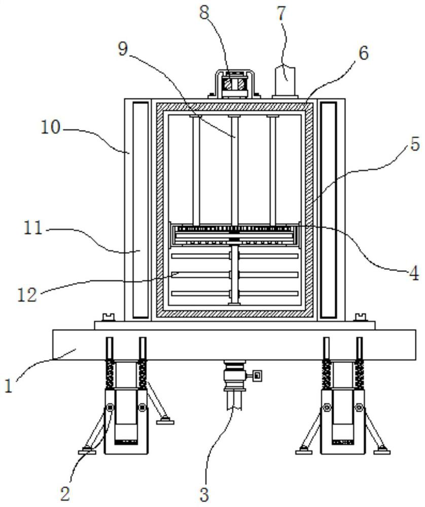
[0026] Example 1: See Figure 1-5 , an anti-glare glass production device with safety protection and a stable base, comprising a base 1, a discharge valve 3 and a housing 5, the four corners at the bottom of the base 1 are respectively fixedly connected with a support structure 2, the base The top end of the seat 1 is fixedly connected with the housing 5, and the bottom end of the housing 5 passes through the base 1 and is fixedly connected with the discharge valve 3. The inside of the outer side of the housing 5 is provided with a heating layer 6, and the top and bottom of the housing 5 are connected to each other. The middle position between the ends is movably connected with a transmission rod 9, and the top end of the transmission rod 9 passes through the housing 5 and is fixedly connected with a servo motor 8. The model of the servo motor 8 can be Y2-80M2-4, and the middle of the transmission rod 9 There is a pulverizing structure 4 between the position and the housing 5....

Embodiment 2

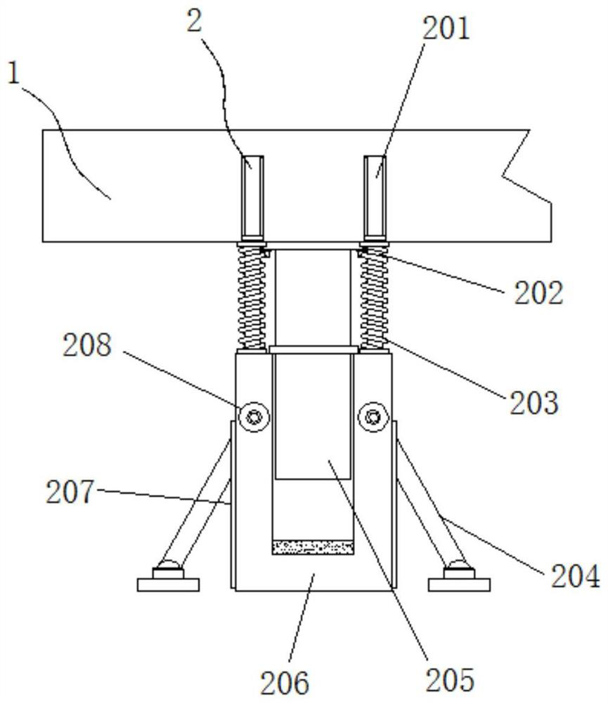
[0029] Embodiment 2: The support structure 2 is composed of a slot 201, an insertion rod 202, a buffer spring 203, a side bar 204, a pillar 205, a sleeve 206, a receiving groove 207 and a fastening bolt 208. The slots 201 are respectively arranged on the base 1 At the four corners of the bottom end, an insertion rod 202 is arranged inside the slot 201, and a sleeve 206 is fixedly connected between the bottom ends of the insertion rod 202, and four sets of buffer springs 203 are arranged between the sleeve 206 and the base 1 , the inside of the sleeve 206 and the base 1 are movably connected with a pillar 205, four sets of storage grooves 207 are arranged on the outside of the sleeve 206, and the inside of the storage groove 207 is provided with a side rod 204, and the connection between the side rod 204 and the sleeve 206 There are fastening bolts 208 in the movable connection;

[0030] The diameter of the insertion rod 202 is smaller than the inner diameter of the slot 201, a...

Embodiment 3

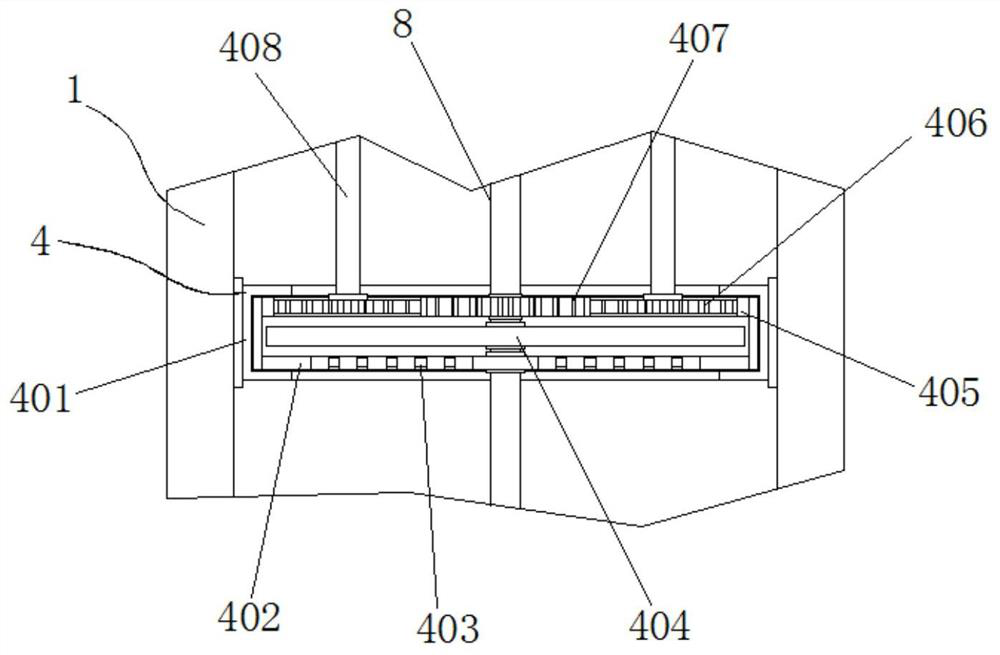
[0032]Embodiment 3: The crushing structure 4 is composed of a limiting groove 401, a turntable 402, a hole 403, a sweeping rod 404, a tooth block 405, a first gear 406, a second gear 407 and a connecting rod 408. The limiting groove 401 is fixedly connected to the shell At the middle position inside the body 5, the inside of the limiting groove 401 is movably connected with a turntable 402, and the bottom end of the turntable 402 is provided with a plurality of groups of holes 403, and the sweep rod 404 is fixedly connected at the middle position of the transmission rod 9, and the top end of the turntable 402 is There are multiple sets of gear blocks 405 fixedly connected inside the housing 5, the connecting rods 408 are respectively fixedly connected to the two sides of the top inside the housing 5, the bottom end of the connecting rods 408 is fixedly connected to the first gear 406, and one side of the first gear 406 A second gear 407 is movably connected between them;

[00...


PUM


Abstract

The invention discloses an anti-glare glass production device with a safety protection and stabilization base, and particularly relates to the technical field of glass production devices. The anti-glare glass production device comprises a base, a discharging valve and a shell, supporting structures are fixedly connected to four corners of the bottom end of the base correspondingly, and the shell is fixedly connected to the top end of the base; and the bottom end of the shell penetrates through the base to be fixedly connected with the discharging valve, and a transmission rod is movably connected to the middle position between the top end and the bottom end in the shell. The supporting structures are fixedly connected to the four corners of the bottom end of the base correspondingly, whenthe weight of the top end of the base is increased, an inserting rod and a supporting column slide into an inserting groove and a sleeve respectively under the action of gravity, a side rod is pulledout from the interior of a storage groove and fixed through a fastening bolt, and then a buffering spring arranged on the outer side of the inserting rod is matched, so that even if sudden impact occurs or the weight of the top is increased or reduced, the horizontal position of the shell cannot be influenced.

Description

technical field [0001] The invention relates to the technical field of anti-glare glass production devices, in particular to an anti-glare glass production device with safety protection and a stable base. Background technique [0002] Anti-glare glass is a special glass that processes the surface of the finished glass. It solves the refraction interference of light in the environment with low reflectivity. Therefore, it is often used in the screen manufacturing of various displays. After production and processing In the beginning, it was often necessary to crush and melt raw materials, but such devices in the past lacked functions such as screening and protection, and had long been eliminated by factories. [0003] In the process of realizing the present invention, the inventors have found that at least the following problems in the prior art have not been resolved: [0004] (1) The outside of the traditional anti-glare glass production device lacks a protective structure, ...

Claims


Application Information

Patent Timeline
Patent Type & Authority Applications(China)
IPC IPC(8): C03B1/00C03B5/16C03B5/187
CPCC03B1/00C03B5/16C03B5/187
Inventor 义通福岑望曹顺英
Owner 郴州市天诚光电科技有限公司
Why Eureka
Try Eureka