
Directional indication road traffic facility suitable for automatic driving of intelligent vehicle

A technology for intelligent vehicles and road traffic, which is applied to vehicle position/route/altitude control, roads, roads, etc., and can solve problems such as increasing the difficulty of identification, judgment, and control, inability to continuously guide and indicate vehicles, and inability to effectively indicate. The guiding signal is clear, suitable for promotion and use, and the effect is easy to implement

Active Publication Date: 2021-03-02
王剑
View PDF24 Cites 0 Cited by
  • Summary
  • Abstract
  • Description
  • Claims
  • Application Information

AI Technical Summary

Problems solved by technology

Generally, there is no marking in the middle of the road intersection, and there are only some left-turn waiting areas. Because the continuous intersection of multiple directions and multiple lanes will form a network of markings and cannot be effectively indicated, the lane markings are disconnected at the intersection and cannot be continuously guided. The vehicle enters the next section of road ahead or on both sides through the intersection
The developing intelligent automatic driving technology is to control the vehicle to drive along the lane on the basis of recognizing the traffic markings. When the lane markings at the intersection are discontinuous, it will increase the difficulty of recognition, judgment and control, resulting in misunderstanding and misjudgment. Security risks

Method used


Image

  • Directional indication road traffic facility suitable for automatic driving of intelligent vehicle
  • Directional indication road traffic facility suitable for automatic driving of intelligent vehicle
  • Directional indication road traffic facility suitable for automatic driving of intelligent vehicle

Examples


Embodiment 1

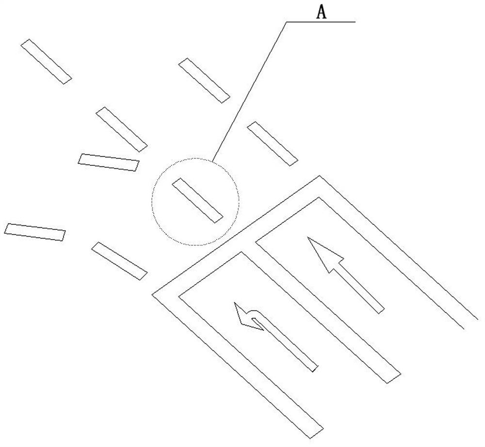
[0037] A directional indication road traffic facility suitable for the automatic driving of intelligent vehicles. It is paved on the road surface of the intersection and is used to guide the intelligent vehicles on the side of the intersection to drive through the intersection according to the preset standard driving trajectory, and drive into the intersection where it is located. in corresponding carriageways on different sides of the intersection.

[0038] The intersection includes common T-junctions, crossroads, etc., and the lanes on each side of the intersection include single-lane, double-lane, and three-lane situations.

[0039] The directional indication road traffic facilities are equipped with marking directional devices for each set of corresponding traffic lanes. The corresponding traffic lanes here are generally two-two correspondence, such as Figure 8 As shown, but depending on the specific road conditions, sometimes a traffic lane also has more than one corres...

Embodiment 2

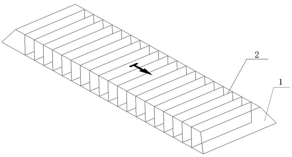
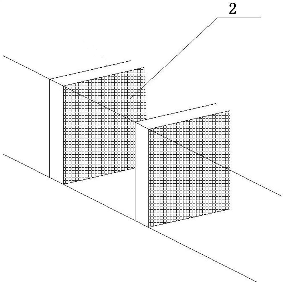
[0055] Such as Figure 4 As shown, what is different from Embodiment 1 is that in this embodiment, the support member of the unit element of the marking line orientation device is composed of a row of elongated prisms, and the display part adopts an indicator light composed of LED lights 3 array. In this embodiment, the supporting member is made of non-transparent hard material, and the LED lamp 3 is installed on the side of each prism facing the direction of the vehicle in an embedded manner. The indication direction of the unit element is affected by the irradiation direction of the LED lamp 3, and through the limitation of the structure such as the lampshade, compared with the passive display sheet, the direction indication effect is better, and the visible range can be further narrowed to avoid damage to Interference with vehicles on other trajectories. At the same time, the LED light indicates a higher intensity, especially suitable for use at night.

Embodiment 3

[0057] Such as Figure 5 As shown, the difference from Embodiment 1 is that in this embodiment, the support member of the single element of the marking line orientation device is composed of two rows of square prisms, and each row includes multiple rows of square prisms. Display parts are installed on the front side of each square prism, and are oriented toward the direction of the vehicle.

[0058] In this embodiment, the support member 1 is preferably made of the same color material as the road surface, such as asphalt color, cement gray and the like. The display part is a white plastic piece.

[0059] The above-mentioned embodiment 1 and embodiment 3 adopt passive display parts, and considering the situation of driving at night, the display parts can be set as colored reflective sheets. And the display parts of embodiment 2 and embodiment 3 can also refer to the third unit element of embodiment 1, for the unit elements of different marking line orientation devices that ar...


PUM


Abstract

The invention discloses a directional indication road traffic facility suitable for automatic driving of an intelligent vehicle. The directional indication road traffic facility is laid on the road surface of an intersection and used for guiding the intelligent vehicles positioned on one side of the intersection to pass through the intersection according to a preset standard driving track and drive into corresponding traffic lanes positioned on different sides of the intersection. The directional indication road traffic facility is characterized in that the directional indication road trafficfacility comprises marking orienting devices arranged for each set of corresponding traffic lanes, each marking orienting device is composed of a plurality of unit pieces arranged in sequence, each unit piece comprises a supporting piece and a display piece, the supporting pieces are fixed to the road surface and protrude out of the road surface, and the display pieces are installed on the supporting pieces and face the vehicle driving-in direction for direction indication, and serve as tracking targets of the intelligent vehicle for detection and recognition According to the invention, when the automatic driving vehicle passes through the intersection, any lane in any direction is indicated by the continuous marking line penetrating through the intersection, so that the safety of automatic driving of the intelligent vehicle is improved.

Description

technical field [0001] The invention belongs to the field of road traffic safety, and in particular relates to a directional indication road traffic facility suitable for the automatic driving of intelligent vehicles. Background technique [0002] In order to ensure traffic safety, it is generally necessary to set up traffic markings on the road, designate lanes, guide vehicles to go their own way, and ensure safe, efficient and smooth passage of vehicles. Generally, there are no markings in the middle of the road intersection, and there are only some left-turn waiting areas. Because the continuous intersection of multiple directions and multiple lanes will form a network of markings and cannot be effectively indicated, the lane markings are disconnected at the intersection and cannot be continuously guided. The vehicle enters the next section of road ahead or on both sides through the intersection. The developing intelligent automatic driving technology is to control the v...

Claims


Application Information

Patent Timeline
Patent Type & Authority Applications(China)
IPC IPC(8): E01F9/506E01F9/582E01F9/588G05D1/02
CPCG05D1/0212G05D1/0234E01F9/506E01F9/582E01F9/588
Inventor 王健
Owner 王剑
Learn More