Telegraph pole mounting machine

A technology for electric poles and machines, which is applied in the field of electric pole installation machines, and can solve the problems of inconvenience, compacting the base of electric pole installation, etc.

Inactive Publication Date: 2021-03-02
张明轩
View PDF9 Cites 1 Cited by
  • Summary
  • Abstract
  • Description
  • Claims
  • Application Information

AI Technical Summary

Problems solved by technology

[0002] Now there is a patent number: CN201720531941.7 An auxiliary device for installing a stable electric utility pole. This utility model relates to an auxiliary device, especially an auxiliary device for installing a stable electric utility pole. The utility model The technical problem to be solved is to provide a stable auxiliary device for installing electric utility poles with high efficiency and high safety performance. In order to solve the above technical problems, the utility model provides such an auxiliary device for installing stable electric utility poles. The device includes a bracket, a wheel, a swing device and a clamping device, etc.; the bottom of the bracket is provided with a swing device, and the right end of the swing device is hingedly connected with a clamping device. The combination of high efficiency and high safety performance is achieved, thus playing an auxiliary role in the installation of utility poles, but the device is not convenient for tamping the installation base of utility poles

Method used


Image

  • Telegraph pole mounting machine
  • Telegraph pole mounting machine
  • Telegraph pole mounting machine

Examples


specific Embodiment approach 1

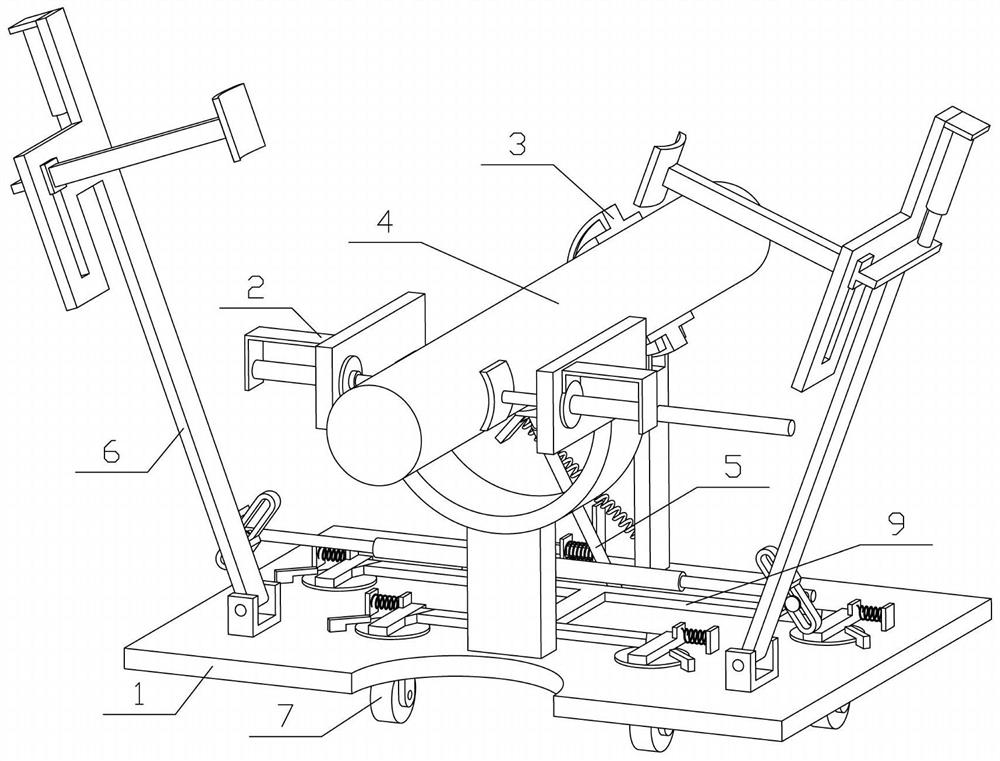
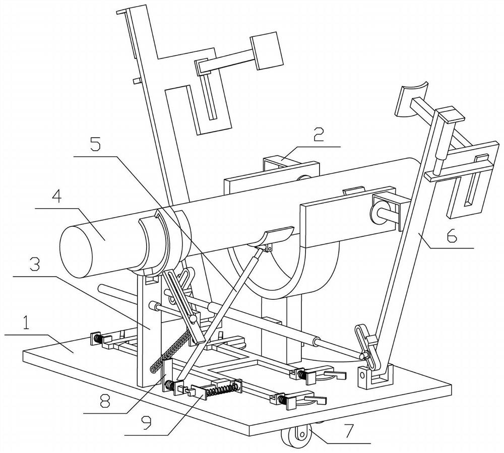
[0034] Combine below Figure 1-13This embodiment is described. The present invention relates to the technical field of utility pole installation machinery, more specifically, a utility pole installation machine, including a carrying device 1, a rotating clamping device 2, a fixing device 3, a utility pole 4, a pushing device 5, a clamping Lifting device 6, rolling device 7, triggering device 8 and pressing device 9, the present invention has the function of being convenient to tamping utility pole installation base.

[0035] Two rotating clamping devices 2 are provided, and the two rotating clamping devices 2 are respectively connected to the left and right ends of the bearing device 1, and the fixing device 3 is fixedly connected to the bearing device 1. The two rotating clamping devices 2 can be Clamp the utility pole 4, the fixing device 3 is attached to the side of the utility pole 4, the pushing device 5 is fixedly connected to the carrying device 1, the pushing device 5 ...

specific Embodiment approach 2

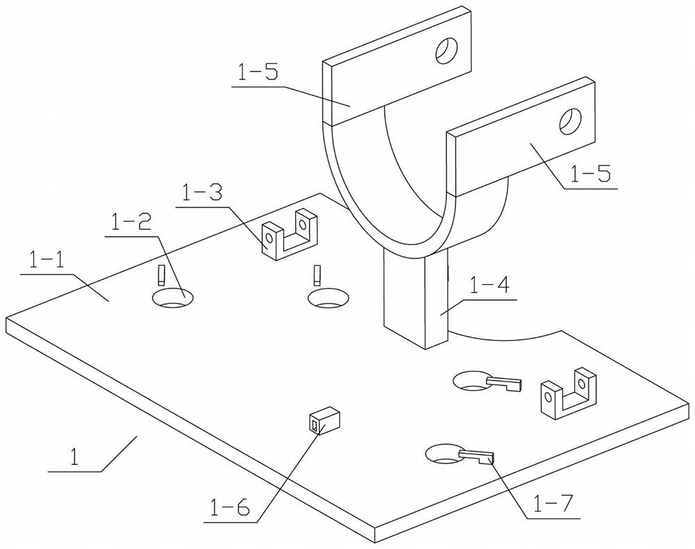
[0037] Combine below Figure 1-13 Describe this embodiment, this embodiment will further explain the first embodiment, the carrying device 1 includes a carrying plate 1-1, a round hole 1-2, a shaft seat 1-3, a vertical column 1-4, an orifice plate 1- 5. The hole block 1-6 and the stopper 1-7, the bearing plate 1-1 is provided with a plurality of round holes 1-2, and the left and right ends of the bearing plate 1-1 are symmetrically fixedly connected with two rotating shaft seats 1-3 , the vertical column 1-4 is fixedly connected on the bearing plate 1-1, the left and right ends of the upper part of the vertical column 1-4 are fixedly connected with the hole plate 1-5, and the bearing plate 1-1 is fixedly connected with the hole block 1-6 , the left and right ends of the bearing plate 1-1 are symmetrically fixedly connected with a plurality of blocking pieces 1-7; when the utility pole 4 is installed in the pit, a plurality of rolling devices 7 are respectively mounted on the b...

specific Embodiment approach 3

[0039] Combine below Figure 1-13 Describe this embodiment, this embodiment will further explain the second embodiment, the said rotary clamping device 2 includes the I-shaped rotating shaft 2-1, the U-shaped plate 2-2, the electric push rod I2-3 and the arc-shaped pressing plate I2 -4, U-shaped plate 2-2 is fixedly connected to the I-shaped rotating shaft 2-1, and the electric push rod I2-3 is fixedly connected to the U-shaped plate 2-2, and the electric push rod I2-3 runs through the I-shaped rotating shaft 2-1 , the movable end of the electric push rod I2-3 is fixedly connected with an arc-shaped pressure plate I2-4, and there are two rotating clamping devices 2, the two clamping devices 2 are symmetrically installed, and the two I-type rotating shafts 2-1 rotate respectively Connected in the two orifice plates 1-5; it can be extended by starting the two electric push rods I2-3, so that the utility pole 4 can be clamped by the two arc-shaped pressure plates I2-4, and the tw...


PUM


Abstract

The invention relates to the technical field of telegraph pole mounting machinery, in particular to a telegraph pole mounting machine. The telegraph pole mounting machine comprises a bearing device, two rotary clamping devices, a fixing device, a telegraph pole, a pushing device, a clamping lifting device, a rolling device, a triggering device and a pressing device, wherein the two rotary clampingdevices are rotationally connected to the left end and the right end of the bearing device correspondingly, the fixing device is fixedly connected to the bearing device, the two rotary clamping devices can clamp the telegraph pole, the fixing device is attached to the side portion of the telegraph pole, the pushing device is fixedly connected to the bearing device, the pushing device is attachedto the side portion of the telegraph pole, the clamping lifting device is fixedly connected with the bearing device, the clamping lifting device can clamp the telegraph pole, the triggering device isfixedly connected to the bearing device, the triggering device is matched with the fixing device, the pressing device is in sliding connection with the bearing device. The telegraph pole mounting machine has the function of conveniently tamping a telegraph pole mounting base layer.

Description

technical field [0001] The invention relates to the technical field of electric pole installation machinery, more specifically, an electric pole installation machine. Background technique [0002] Now there is a patent number: CN201720531941.7 An auxiliary device for installing a stable electric utility pole. This utility model relates to an auxiliary device, especially an auxiliary device for installing a stable electric utility pole. The utility model The technical problem to be solved is to provide a stable auxiliary device for installing electric utility poles with high efficiency and high safety performance. In order to solve the above technical problems, the utility model provides such an auxiliary device for installing stable electric utility poles. The device includes a bracket, a wheel, a swing device and a clamping device, etc.; the bottom of the bracket is provided with a swing device, and the right end of the swing device is hingedly connected with a clamping dev...

Claims


Application Information

Patent Timeline
IPC IPC(8): E04H12/34
CPCE04H12/34
Inventor 张明轩
Owner 张明轩
Why Eureka
Try Eureka