
Door lock with controllable reverse lifting function

A technology of door lock and function, which is applied in the field of door locks with controllable anti-lifting function, and can solve the problems of inability to accurately close the anti-lifting function of the lock body, trouble, lack of positioning of the transmission disc, etc.

Pending Publication Date: 2021-03-02
温州双纳科技有限公司
View PDF1 Cites 0 Cited by
  • Summary
  • Abstract
  • Description
  • Claims
  • Application Information

AI Technical Summary

Problems solved by technology

However, there is no structure for positioning the transmission disc in the adjustment mechanism, and the state of the transmission disc when restricting the reverse rotation of the transmission shaft cannot be kept stable, that is, the user cannot stably and accurately control the anti-lifting function of the lock body
For example, when the user needs to close the anti-lift function of the lock body, but the transmission plate in the lock body is shifted due to the lack of corresponding positioning structure during use, the lock body cannot accurately close the anti-lift function of the lock body
Therefore, if the adjustment of the anti-lifting function in the lock body is disordered, it will also cause greater trouble for the user when unlocking. To realize the control of the anti-lifting function of the lock body, in addition to having a corresponding adjustment mechanism, the adjustment mechanism The positioning structure of the

Method used


Image

  • Door lock with controllable reverse lifting function
  • Door lock with controllable reverse lifting function
  • Door lock with controllable reverse lifting function

Examples


Embodiment Construction

[0037] In order to make the purpose, technical solution and advantages of the present invention clearer, the technical solution of the present invention will be described in detail below. Apparently, the described embodiments are only some of the embodiments of the present invention, but not all of them. Based on the embodiments of the present invention, all other implementations obtained by persons of ordinary skill in the art without making creative efforts fall within the protection scope of the present invention.

[0038] Below in conjunction with accompanying drawing, the present invention will be further described with specific embodiment,

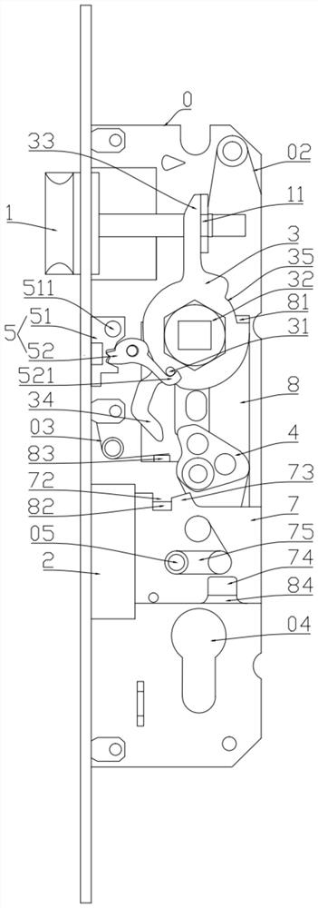
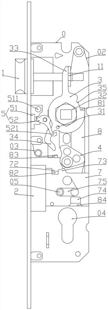
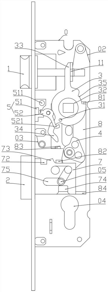
[0039] Such as Figure 1-10 As shown, a door lock that can control the anti-lifting function includes a housing 0, and the housing 0 is provided with a latch tongue 1 and a square tongue 2 that can extend or retract the housing 0, and is used to drive the The bolt driver 3 for the movement of the bolt 1 and the square tongue driver...


PUM


Abstract

The invention belongs to the technical field of door locks, and particularly relates to a door lock with a controllable reverse lifting function. The door lock with the controllable reverse lifting function comprises a shell body, a latch bolt, a dead bolt, a latch bolt driving piece which is used for driving the latch bolt to move and a dead bolt driving piece which is used for driving the dead bolt to move, the latch bolt driving piece can control the dead bolt driving piece to rotate through reverse rotation and drive the dead bolt to stretch out of the shell body, a reverse lifting controlassembly capable of limiting reverse rotation of the latch bolt driving piece is arranged in the shell body, the reverse lifting control assembly comprises a driving switch capable of moving up and down and a rotatable locking piece, the driving switch drives the locking piece to rotate through up-down movement, a lock hook is formed on the locking piece, a limiting shaft capable of being hookedby the lock hook is formed on the latch bolt driving piece, a positioning piece capable of extending outwards and a spring which abuts against the positioning piece are arranged in the drive switch, the spring enables the positioning piece to have trend of extending out of the driving switch, and a positioning through hole allowing the positioning piece to be embedded therein is formed in one endof the shell body. The door lock can achieve stable control over the reverse lifting function.

Description

technical field [0001] The invention belongs to the technical field of door locks, and relates to a door lock capable of controlling the lifting function. Background technique [0002] As a device for locking the door of a house, the door lock can protect the safety of the user's life and property. For this purpose, the existing door locks often have an anti-lock function, and the user can lock the door by turning the key outdoors. In order to make the anti-lock function more convenient, some door locks will also add an anti-lift function. The user only needs to turn the handle on the door in the opposite direction to realize the anti-lock of the door. [0003] Because after the door is back locked, the door lock must be opened by a key, so in some specific cases, the anti-lifting function of the door lock will also cause a lot of inconvenience to the user. If the user turns the handle in the opposite direction to lock the door but forgets to bring the key when going out, t...

Claims


Application Information

Patent Timeline
IPC IPC(8): E05B15/00E05B15/10
CPCE05B15/00E05B15/10
Inventor 姜芳伟
Owner 温州双纳科技有限公司
Learn More