
High-strength suspension insulator for ultra-high voltage power transmission line

A suspension insulator, transmission line technology, applied in suspension/strain insulators, circuits, insulators, etc., can solve the problems of insufficient stability of high-voltage line installation, insufficient toughness and strength, and ineffective heat dissipation of high-voltage transmission lines. Good skirt strength, easy to dissipate heat and reduce impact

Active Publication Date: 2021-03-02
JIANGSU SOUTH PORCELAIN INSULATOR CO LTD
View PDF15 Cites 0 Cited by
  • Summary
  • Abstract
  • Description
  • Claims
  • Application Information

AI Technical Summary

Problems solved by technology

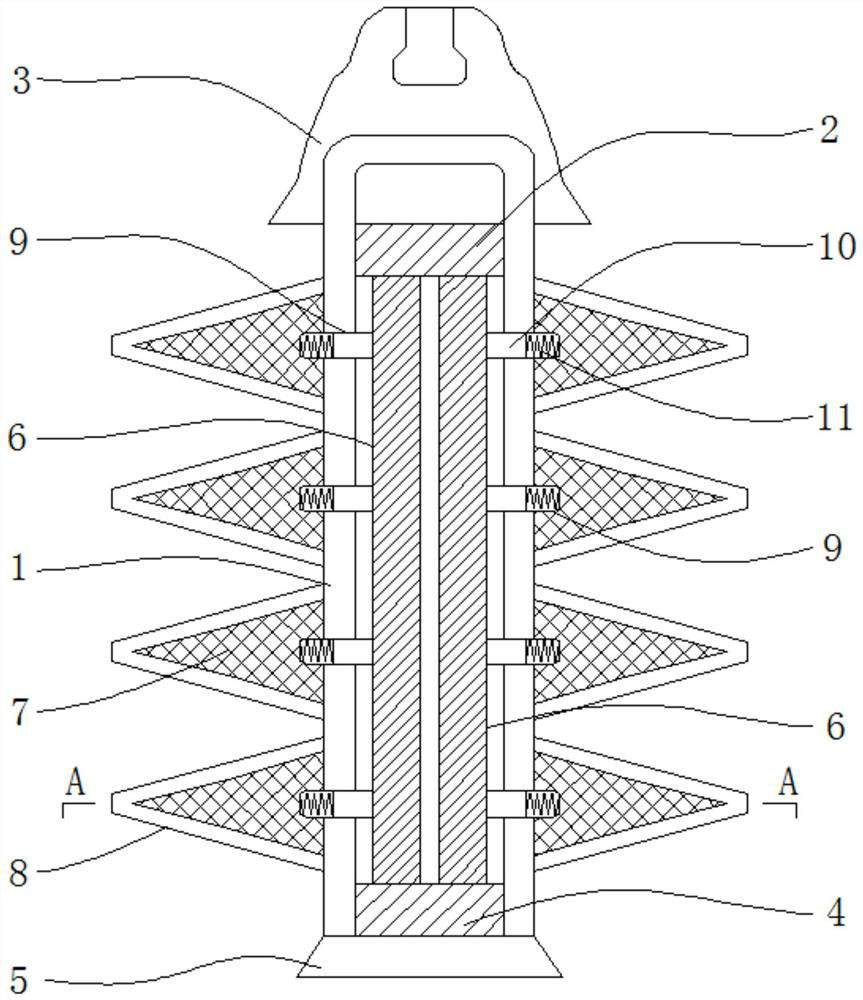
[0003] In the prior art, insulators are necessary installation components for high-voltage transmission lines and are widely used in electronic systems. The existing insulator structure includes internal mandrels, external sheds and necessary connecting components at both ends; and the use of insulators is usually It has two functions. On the one hand, the distance between the outer sheds is to realize the creepage phenomenon of high-voltage lines; while the inner mandrel is to support and fix high-voltage lines, effectively overhead transmission lines; and in the UHV transmission lines in the prior art Due to the high-voltage state, high-strength insulators are needed to support the overhead lines. In the existing insulators, the inner mandrel is usually provided as a whole, and the shed structure is directly connected to the mandrel. In this structure, on the one hand, the mandrel is set as a whole, and the toughness and strength are not enough; on the other hand, the mandrel is integrated with the outer shed, and there is no gap inside, so the heat generated by the high-voltage transmission line cannot be effectively dissipated, resulting in the installation of high-voltage lines. not stable enough

Method used


Image

  • High-strength suspension insulator for ultra-high voltage power transmission line
  • High-strength suspension insulator for ultra-high voltage power transmission line

Examples


Embodiment Construction

[0016] The present invention will be further illustrated below in conjunction with the accompanying drawings and specific embodiments. This embodiment is implemented on the premise of the technical solution of the present invention. It should be understood that these embodiments are only used to illustrate the present invention and are not intended to limit the scope of the present invention.

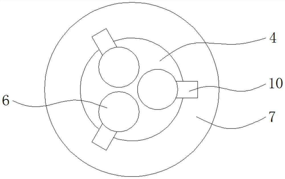
[0017] like figure 1 and figure 2 As shown, a high-strength suspension insulator for UHV transmission lines includes an outer insulating shell 1, and a fixed upper fitting 2 is installed inside the upper end of the outer insulating shell 1, and the outer insulating shell 1 An integrated steel cap structure 3 is provided at the upper end; a lower fitting 4 is installed inside the lower end of the outer insulating shell 1, and a connecting ball head 5 is installed at the lower end of the outer insulating shell 1; and the outer insulating shell 1 1. Several insulating mandrels 6 are corr...


PUM


Abstract

The invention discloses a high-strength suspension insulator for an ultra-high voltage power transmission line. The high-strength suspension insulator comprises an outer insulating shell body, whereina fixed upper hardware fitting is correspondingly arranged in the upper end of the outer insulating shell body, and an integrated steel cap structure is correspondingly arranged at the upper end partof the outer insulating shell body; and a lower fitting is correspondingly installed in the lower end of the outer insulating shell body, and a connecting ball head is correspondingly installed at the lower end of the outer insulating shell body. The suspension insulator in the invention is of a high-strength and buffer-type combined insulator structure, the strength is improved through a plurality of insulating core rods between the upper hardware fitting and the lower hardware fitting, and stress is dispersed by increasing gaps; and spring pieces are mounted on the insulating core rods andspring grooves are formed in the insulating shell body, the corresponding spring pieces are used for buffering in mounting, so that the overall structure is more reasonable, and the strength is higher.

Description

technical field [0001] The invention relates to the field of insulator equipment in power systems, in particular to a high-strength suspension insulator for extra-high voltage transmission lines. Background technique [0002] In the prior art, in order to increase and ensure the mechanical strength, especially the strength of ceramic parts used in insulators, it is necessary to design the raw materials and mechanical strength of the insulator, and the design of the mechanical strength is usually designed from the characteristics of the insulator components, including electrical characteristics It is very important to use high-strength insulators in the work of high-voltage transmission lines for beam design, mechanical properties and aging characteristics. [0003] In the prior art, insulators are necessary installation components for high-voltage transmission lines and are widely used in electronic systems. The existing insulator structure includes internal mandrels, extern...

Claims


Application Information

Patent Timeline
IPC IPC(8): H01B17/02H01B17/06H01B17/54H01B17/40
CPCH01B17/02H01B17/06H01B17/54H01B17/40
Inventor 胡秦然杨生哲高琍玲刘少华徐秀娟
Owner JIANGSU SOUTH PORCELAIN INSULATOR CO LTD
Learn More