Multifunctional milling cutter

A multi-functional milling cutter technology, applied in the direction of milling cutters, milling machine equipment, manufacturing tools, etc., can solve the problems of single function, low milling cutter strength, low efficiency, etc., to achieve increased strength, enhanced installation fixity, and work efficiency high effect

Inactive Publication Date: 2021-03-05
常州市博裕数控刀具有限公司
View PDF0 Cites 0 Cited by
  • Summary
  • Abstract
  • Description
  • Claims
  • Application Information

AI Technical Summary

Problems solved by technology

Most of the milling cutters on the market can only be used for cutting and have a single function. For the continuous processing of the workpiece, the efficiency is low. In addition, the installation of the tool holder is only fixed by screws, which is not strong in fixation, and the strength of the milling cutter is not high.

Method used


Image

  • Multifunctional milling cutter
  • Multifunctional milling cutter
  • Multifunctional milling cutter

Examples


Embodiment 1

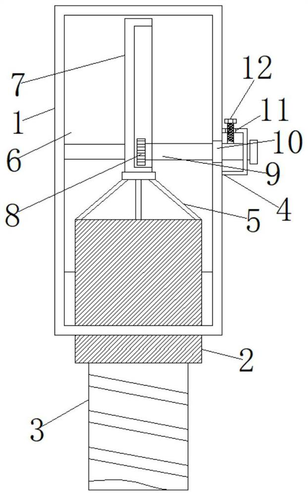
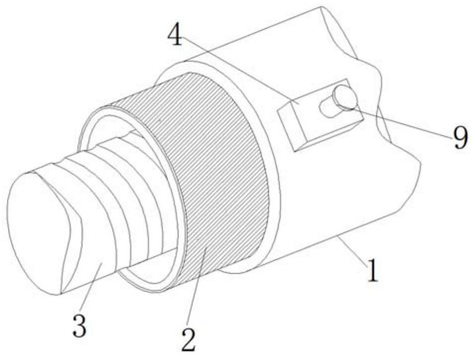
[0024] Embodiment 1, when the milling cutter is installed, the movable block 18 is inserted into the inside of the lace slot 17, and then the movable block 18 is rotated so that the second screw hole 20 is aligned with the second screw rod 19, and at the same time the convex surface of the movable block 18 is Compress with the concave surface of the lace slot 17, so that the movable block 18 is stuck in the inside of the lace slot 17, and then the second screw 19 is screwed to the inside of the second screw hole 20 to complete the installation of the tool bar 3. Reinforcement strengthens the fixity of the knife bar 3 and improves the strength of the knife bar 3 .

Embodiment 2

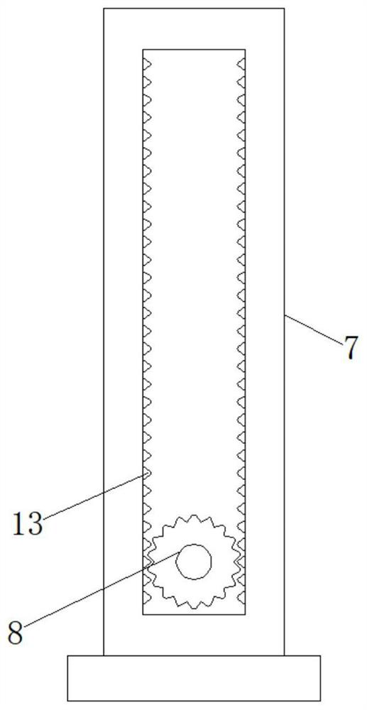
[0025] Embodiment 2, when the equipment is in use, the cutter bar 3 can be used for cutting processing, and the workpiece can also be polished through the grinding ring 2. After the user rotates the rotating shaft 9, the rotating shaft 9 drives the gear 8 to rotate, and acts on the rack 13 slides on the support bar with the sliding plate 7, so that the sliding plate 7 pushes the grinding ring 2 to slide inside the ring groove 15, so that the grinding ring 2 is placed outside the ring groove 15, and can also be retracted inside the ring groove 15 to adjust Conveniently, after tightening the first screw rod 12 afterwards, one end of the first screw rod 12 presses the rotating shaft 9, so that the position of the sliding plate 7 is fixed.


PUM


Abstract

The invention belongs to the technical field of metal cutting tools, and particularly relates to a multifunctional milling cutter which comprises a cutter holder and a cutter bar. An inner cavity, anannular groove and a lace groove hole are formed in the cutter holder, the interior of the inner cavity is communicated with the interior of the annular groove, a grinding ring is embedded in the annular groove, a grinding layer is arranged on the outer side of the grinding ring, a support is welded to the top of the grinding ring, a sliding plate is connected to the top of the support through rivets, the sliding plate is slidably arranged in the inner cavity, a groove is formed in one side of the sliding plate, a rack is welded to the inner wall of the groove, a gear is engaged and connectedwith the rack, a rotating shaft is welded to a center shaft on one side of the gear, the rotating shaft is rotatably mounted on one side of the cutter holder, a mounting plate is welded to one end ofthe cutter bar, and a movable block is welded to one side of the mounting plate. The multifunctional milling cutter has multifunctional and high-strength characteristics.

Description

technical field [0001] The invention belongs to the technical field of metal cutting tools, and in particular relates to a multifunctional milling tool. Background technique [0002] A milling cutter is a rotating tool with one or more teeth for milling. When working, each knife tooth cuts off the allowance of the workpiece intermittently in turn. Milling cutters are mainly used for machining planes, steps, grooves, forming surfaces and cutting off workpieces on milling machines. Most of the milling cutters on the market can only be used for cutting and have a single function. For the continuous processing of the workpiece, the efficiency is low. In addition, the installation of the tool holder is only fixed by screws, which is not strong in fixation, and the strength of the milling cutter is not high. Contents of the invention [0003] The technical problem to be solved by the present invention is to provide a multi-functional milling cutter with multi-functional and hi...

Claims


Application Information

Patent Timeline
Patent Type & Authority Applications(China)
IPC IPC(8): B23C5/00
CPCB23C5/00
Inventor 谢燕华
Owner 常州市博裕数控刀具有限公司
Why Eureka
Try Eureka