Clutch control mechanism and vehicle

A clutch control and release bearing technology, which is applied to clutches, mechanical drive clutches, mechanical equipment, etc., can solve the problems of large driving force and short lever arm, and achieve low driving force demand, small friction force, and easy lightweight Effect

Pending Publication Date: 2021-03-05
BYD CO LTD
View PDF9 Cites 0 Cited by
  • Summary
  • Abstract
  • Description
  • Claims
  • Application Information

AI Technical Summary

Problems solved by technology

[0004] The technical problem to be solved by the present invention is: for the existing clutch operating device, the rotating shaft of the lever actuator is on the same side as the lever actuator, and the right end of the actuating clutch is on the other side of the lever actuator. To solve the problem that the driving lever arm is relatively short and the required driving force is large, a clutch control mechanism and a vehicle are provided

Method used


Image

  • Clutch control mechanism and vehicle
  • Clutch control mechanism and vehicle
  • Clutch control mechanism and vehicle

Examples


Embodiment Construction

[0039] In order to make the technical problems, technical solutions and beneficial effects solved by the present invention clearer, the present invention will be further described in detail below in conjunction with the accompanying drawings and embodiments. It should be understood that the specific embodiments described here are only used to explain the present invention, not to limit the present invention.

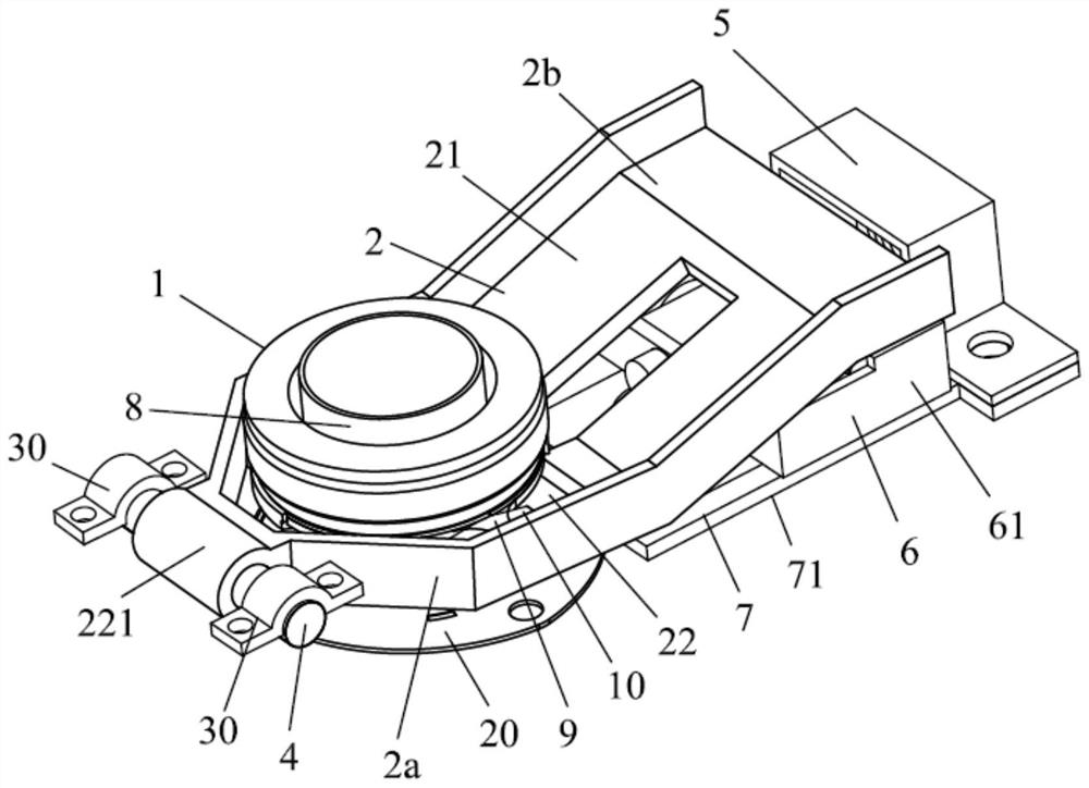
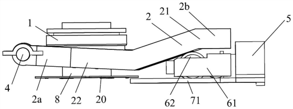
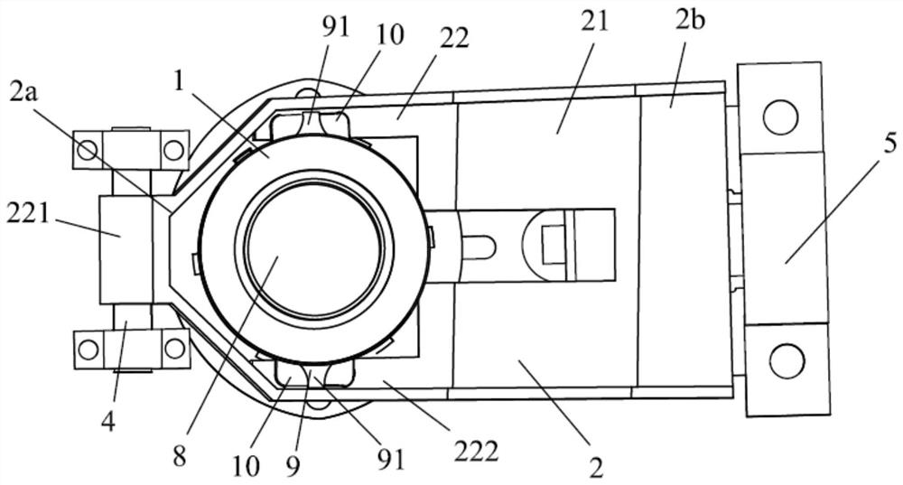
[0040] Such as Figure 1 to Figure 6 As shown, the embodiment of the present invention provides a clutch control mechanism, including a release bearing 1, an actuator frame 2 and a driving device. The first end 2a of the actuator frame 2 is rotatably connected to the transmission housing through the support pin 4, and the first end 2a of the actuator frame 2 is used to place and support the release bearing 1. The driving device applies a driving force to the load-bearing portion of the second end of the actuator frame 2 to make the actuator frame 2 swing around the axis...


PUM


Abstract

The invention belongs to the technical field of clutch control mechanisms, and particularly relates to a clutch control mechanism and a vehicle. The clutch control mechanism comprises a release bearing; an executing frame, wherein the first end part of the executing frame is rotatably connected to a transmission shell through a supporting pin shaft; and a driving device, wherein the driving deviceapplies driving force to a force bearing part at the second end part of the executing frame, so that the executing frame swings around the axis of the supporting pin shaft, the release bearing is pushed to move in the direction close to or far away from a clutch so as to control the engagement or disengagement of the clutch, wherein the supporting pin shaft and the force bearing part at the second end part of the executing frame are positioned on the two sides of the release bearing. According to the clutch control mechanism, due to the fact that the supporting pin shaft and the force bearingpart at the second end part of the executing frame are located on the two sides of the release bearing, a lever force arm is lengthened to achieve the labor-saving effect, and the driving force requirement of the driving device is lower.

Description

technical field [0001] The invention belongs to the technical field of clutch operating mechanisms, and in particular relates to a clutch control mechanism and a vehicle. Background technique [0002] An existing operating device for a friction disc clutch comprises: a lever actuator; an operating device for turning the lever actuator around a turning axis so that force is applied by means of the lever actuator to the friction disc clutch; and, a reset means for applying a reset torque to the lever actuator about the rollover axis. Furthermore, a damping device is provided for applying a predetermined damping torque to the lever actuator about the pivot axis. The actuating device has a roller which is arranged between the lever actuator and an abutment element and which can be moved along the lever actuator in order to vary the distance between the abutment element and the lever actuator. [0003] With this type of clutch actuating device, by actuating the actuator, the ro...

Claims


Application Information

Patent Timeline
Patent Type & Authority Applications(China)
IPC IPC(8): F16D23/14
CPCF16D23/143F16D2023/141
Inventor 廉玉波凌和平翟震熊雨超王文静
Owner BYD CO LTD
Why Eureka
Try Eureka