Lubrication system for a vibratory pile driver
A lubricating system, pile driver technology, applied in the direction of engine lubrication, lubrication pump, engine components, etc., can solve the problems of needing a pile driver, lack of lubrication to increase bearing wear, expensive maintenance and downtime
- Summary
- Abstract
- Description
- Claims
- Application Information
AI Technical Summary
Problems solved by technology
Method used
Image
Examples
Embodiment Construction
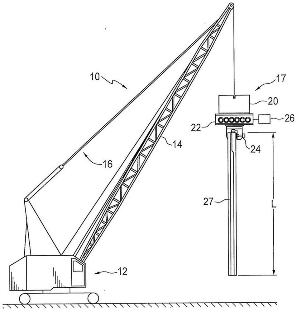
[0009] figure 1 It is a schematic diagram of a routine vibrating pile driver system, and is shown in 10. It includes a conventional building crane 12 having an extended boom 14 and a control cable system 16. At the end 18 of the boom 14, the control cable extends down to the vibration pile driver assembly 17. The assembly typically includes suppressor 20, gearbox 22, and clamping system 24 and drive motor 26 for the assembly, usually hydraulic, although it can also be an electric motor. All of these components are routine, so there is no need to explain. The jig 24 clamps the gearbox and the suppressor to the pile 27 of the length L, which will be driven in the operation.
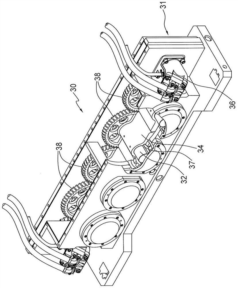
[0010] figure 2 A conventional vibration pile driver gearbox is shown. In general, the gearbox shown in 30 includes a housing 31 that is typically made of steel. Although the size of the housing can vary, the typical system will be 14 inches × 96 inch x 24 inches, which is merely exemplary. At the bottom of...
PUM
 Abstract
Description
Claims
Application Information
 - R&D
- Intellectual Property
- Life Sciences
- Materials
- Tech Scout
- Unparalleled Data Quality
- Higher Quality Content
- 60% Fewer Hallucinations
Browse by: Latest US Patents, China's latest patents, Technical Efficacy Thesaurus, Application Domain, Technology Topic, Popular Technical Reports.
© 2025 PatSnap. All rights reserved.Legal|Privacy policy|Modern Slavery Act Transparency Statement|Sitemap|About US| Contact US: help@patsnap.com


