LED control unit circuit
A control unit and circuit technology, applied in the direction of electrical components, etc., can solve the problems of large space required, high production cost, and difficult to market
- Summary
- Abstract
- Description
- Claims
- Application Information
AI Technical Summary
Problems solved by technology
Method used
Image
Examples
Embodiment 1
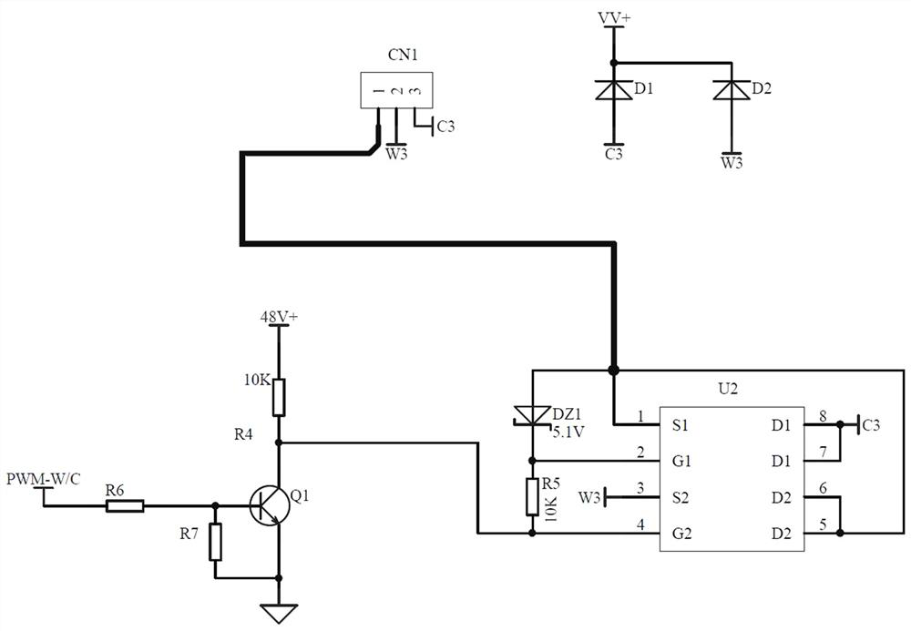
[0024] Embodiment 1: When the control unit is a triode Q1 and a resistor R6, the second field effect transistor is a P-channel field effect transistor, and the third field effect transistor is an N-channel field effect transistor.
[0025] When the intelligent module outputs, the module provides a pwm square wave. When the output is high, the output of transistor Q1 is low. At this time, the gate of the second field effect transistor is low, and the second field effect transistor is turned on. At this time, the LED lights up in cool white light, and the third FET is cut off;
[0026] When the intelligent module outputs a low level, the transistor Q1 is cut off, and the diode DZ1 is charged through the resistors R3 and R4. At this time, the gate of the third field effect transistor is 10V, and the third field effect transistor is turned on. At this time, the warm white light is on. When the intelligent module continuously outputs the PWM signal, the dimming and color adjustment...
Embodiment 3
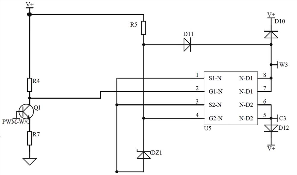
[0029] Embodiment 3: the control unit is an N-channel FET, the drain is connected to VCC, the S pole is connected to the ground, the second FET is a P-channel FET, and the third FET is an N-channel FET;
[0030] When the intelligent module outputs, the module provides a pwm square wave. When the output is high level, the output of the first field effect transistor is high level. At this time, the gate of the second field effect transistor is high level, and the second field effect transistor Cut-off, at this time, the LED light is warm white, and the third FET is turned on;
[0031] When the intelligent module outputs a low level, the first field effect transistor is cut off, and the second field effect transistor is turned on, and the cool white light is on at this time. When the intelligent module continuously outputs the PWM signal, the dimming and color adjustment of the LED can be realized.
Embodiment 4
[0032] Embodiment 4: the control unit is an N communication field effect transistor, the drain is connected to VCC, the S pole is connected to the ground electrode, and the second field effect transistor and the third field effect transistor are N communication field effect transistors;
[0033] When the intelligent module outputs, the module provides a pwm square wave. When the output is high level, the output of the first field effect transistor is high level. At this time, the gate of the second field effect transistor is high level, and the second field effect transistor Conduction, at this time the LED light is on with cool white light, and the third field effect tube is cut off;
[0034] When the intelligent module outputs a low level, the first field effect transistor is cut off, the second field effect transistor is cut off, and the third field effect transistor is turned on. At this time, the temperature is warm and bright. When the intelligent module continuously out...
PUM
 Abstract
Description
Claims
Application Information
 - R&D
- Intellectual Property
- Life Sciences
- Materials
- Tech Scout
- Unparalleled Data Quality
- Higher Quality Content
- 60% Fewer Hallucinations
Browse by: Latest US Patents, China's latest patents, Technical Efficacy Thesaurus, Application Domain, Technology Topic, Popular Technical Reports.
© 2025 PatSnap. All rights reserved.Legal|Privacy policy|Modern Slavery Act Transparency Statement|Sitemap|About US| Contact US: help@patsnap.com


