Grabbing method for flexible pneumatic manipulator

A pneumatic manipulator and flexible technology, applied in manipulators, chucks, manufacturing tools, etc., can solve the problems of poor versatility of gripping equipment and high cost of use, and achieve the effects of convenient and quick replacement, high grasping force, and reduced use cost.

Inactive Publication Date: 2021-03-09
南京荧河谷科技有限公司
View PDF0 Cites 2 Cited by
  • Summary
  • Abstract
  • Description
  • Claims
  • Application Information

AI Technical Summary

Problems solved by technology

[0002] At present, one type of clamping equipment is usually only suitable for one type of workpiece clamping work. For different workpieces, different types of clamping equipment need to be replaced to match, resulting in poor versatility of the clamping equipment and high cost of use.

Method used


Image

  • Grabbing method for flexible pneumatic manipulator
  • Grabbing method for flexible pneumatic manipulator
  • Grabbing method for flexible pneumatic manipulator

Examples


Embodiment Construction

[0028] The present invention will be described in further detail below in conjunction with the accompanying drawings and specific embodiments, and the implementation scope of the present invention is not limited thereto.

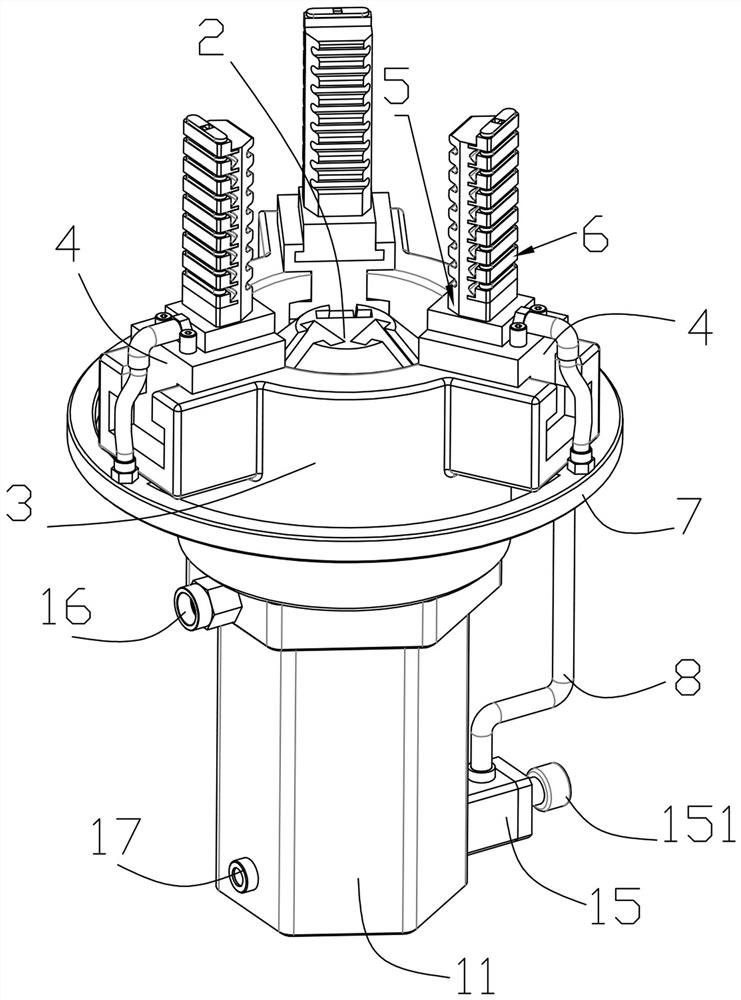
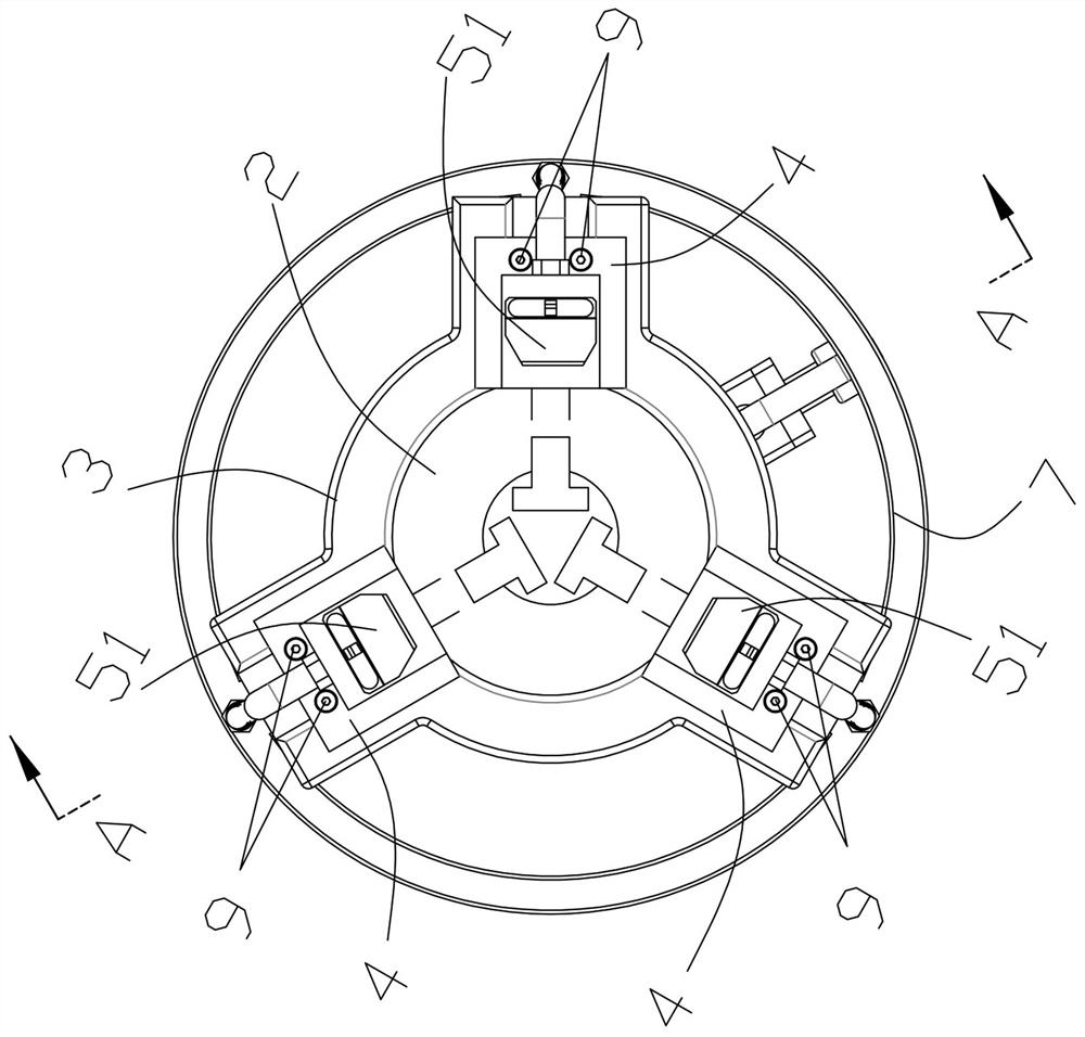
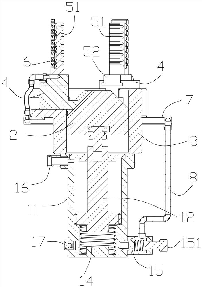
[0029] Such as Figure 1 to Figure 12 As shown, the grasping method of a flexible pneumatic manipulator described in this embodiment includes a power cylinder 1, a tapered slide table 2 and a guide tube seat 3; the power cylinder 1 includes a cylinder body 11, a piston rod 12, Cylinder end cover 13, back-moving spring 14, overflow valve 15, air pipe joint 16 and intake check valve 17, described cylinder end cover 13 is fixed on one end of cylinder body 11, between described cylinder end cover 13 and cylinder body 11 A cylinder chamber is formed between them, the piston rod 12 is arranged in the cylinder chamber, the cylinder chamber is divided into an upper chamber and a lower chamber by the piston rod 12, and one end of the piston rod 12 passes through the ...


PUM


Abstract

The invention discloses a grabbing method for a flexible pneumatic manipulator. The method comprises a power air cylinder, a conical sliding table, a guide round pipe seat and an air supply circular ring, wherein the power air cylinder comprises an air cylinder body, a piston rod, an air cylinder end cover, a reset spring, an overflow valve, an air pipe connector and an air inlet one-way valve; the reset spring is arranged in a lower cavity of the air cylinder body; the air pipe connector is communicated with an upper cavity of the air cylinder body; the overflow valve and the air inlet one-way valve are respectively communicated with the lower cavity of the air cylinder body; the conical sliding table and the piston rod are movably clamped; the guide round pipe seat is fixed at one end ofthe air cylinder body and is in sliding connection with a sliding block seat which is further in sliding connection with the conical sliding table; a pneumatic deformation claw is clamped on the sliding block seat in a sliding manner; the pneumatic deformation claw is provided with a row of air claw ejection pieces; the air claw ejection pieces are sequentially hinged together; the air supply circular ring is communicated with the overflow valve; and the air supply circular ring is communicated with the air claw ejection pieces. The method can adapt to workpieces with larger appearance changes and adapt to more types of workpieces, the application range is expanded, and the use cost is reduced.

Description

technical field [0001] The invention relates to the technical field of gripping equipment, in particular to a gripping method of a flexible pneumatic manipulator. Background technique [0002] At present, one type of clamping equipment is usually only suitable for clamping one type of workpiece. For different workpieces, different types of clamping equipment need to be replaced to match, resulting in poor versatility of the clamping equipment and high cost of use. Contents of the invention [0003] The object of the present invention is to overcome the above-mentioned shortcomings and provide a grasping method of a flexible pneumatic manipulator. [0004] To achieve the above object, the specific scheme of the present invention is as follows: [0005] A grabbing method for a flexible pneumatic manipulator, comprising a power cylinder, a tapered slide and a guide tube seat; Air check valve, the cylinder end cover is fixed at one end of the cylinder body, a cylinder chambe...

Claims


Application Information

Patent Timeline
Patent Type & Authority Applications(China)
IPC IPC(8): B25J15/00B25J15/10
CPCB25J15/0023B25J15/10
Inventor 华玉香
Owner 南京荧河谷科技有限公司
Why Eureka
Try Eureka