
A new synthetic fiber cotton molding method and processing equipment

A synthetic fiber and molding technology, applied in the field of brand-new synthetic fiber cotton molding methods and processing equipment, can solve the problems of not being able to produce products with complex shapes, not having too many pieces, and not being complicated in paving and filling operations. , to achieve the effect of realizing the processing function

Active Publication Date: 2022-04-12
赛乐福(连云港)复合材料有限公司
View PDF0 Cites 0 Cited by
  • Summary
  • Abstract
  • Description
  • Claims
  • Application Information

AI Technical Summary

Problems solved by technology

[0006] The mold filling time should be as short as possible to prevent too much temperature loss of the pieces from affecting the combination of each layer of pieces, so the filling operation should not be complicated, and the number of pieces should not be too large, so products with complex shapes cannot be produced, so it is necessary to carry out Improve

Method used


Image

  • A new synthetic fiber cotton molding method and processing equipment
  • A new synthetic fiber cotton molding method and processing equipment
  • A new synthetic fiber cotton molding method and processing equipment

Examples


Embodiment 1

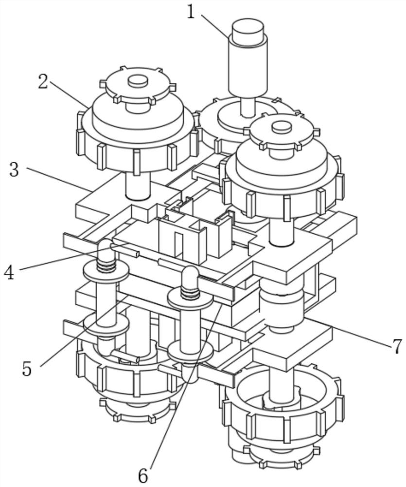
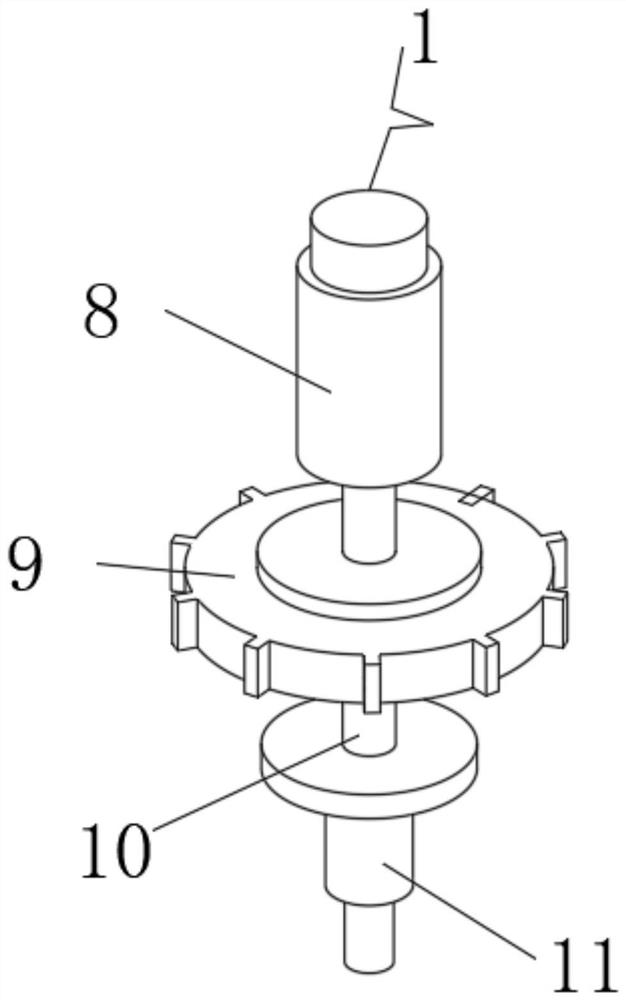
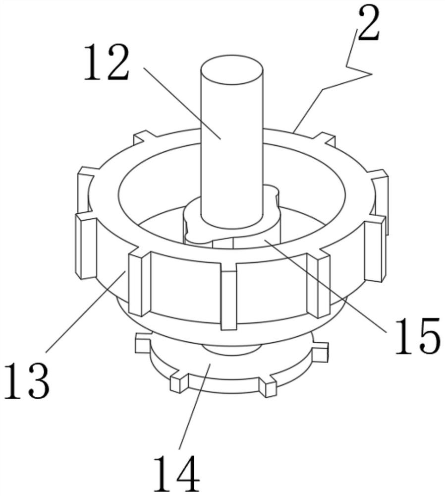
[0043] A brand new synthetic fiber cotton molding processing equipment, such as Figure 1-8 As shown, it includes a transmission device 1, a transmission device 2 is rotatably connected to the side end position of the transmission device 1, the lower end of the transmission device 2 is connected to a limit device 3, and a connection device 4 is clamped at the squat position of the limit device 3. , the lower end of the connecting device 4 is fixedly connected with the upper die 6, the lower end of the upper die 6 is in contact with the lower die 5, the central rear end of the transmission device 1 and the transmission device 2 are inserted with a fixing device 7, and the transmission device 1 Including the motor 8, the first toothed plate 9, the connecting shaft 10 and the plug-in shaft 11, the motor 8 is installed on the top of the inner end of the transmission device 1, the lower end of the motor 8 is rotatably connected with the first toothed plate 9, the center of the first...

Embodiment 2

[0047] On the basis of Example 1, as Figure 9-10 As shown, the lower mold 5 also includes a first communication pipe 34, a first square pipe 35 and a first outer pipe 36. The first communication pipe 34 is provided at the side end of the first airtight cover 24, and the first communication pipe 34 passes through The first square pipe 35 is communicated with the first outer pipe 36, and the upper mold 6 also includes a second communication pipe 37, a second square pipe 38 and a second outer pipe 39. The second communication pipe 37 is provided in the second airtight cover. 27 , the second communication pipe 37 is communicated with the second outer pipe 39 through the second square pipe 38 .

[0048] When this embodiment is in use, the first communication pipe 34, the first square pipe 35 and the first outer pipe 36, which are additionally provided at the inner end of the lower mold 5, and the second communication pipe 37, the first outer pipe 36, and the second communication p...


PUM


Abstract

The invention discloses a brand-new synthetic fiber cotton molding method and processing equipment, including a transmission device, a transmission device is rotatably connected to the side end of the transmission device, and the lower end of the transmission device is connected to a limiting device through, The squatting position of the limiting device is clamped with a connecting device, the lower end of the connecting device is fixedly connected with an upper mold, the lower end of the upper mold is connected with a lower mold, the transmission device and the transmission device The rear end of the center is plugged with a fixing device. The transmission device includes a motor, a first toothed disc, a connecting shaft and an insertion shaft. The motor is installed on the top of the inner end of the transmission device. A toothed disc, the center of the first toothed disc is connected with a connecting shaft through it. The invention is a brand-new synthetic fiber cotton molding method and processing equipment, through the setting of the conduction device, the purpose of inner end conduction is realized.

Description

technical field [0001] The invention relates to the technical field of molding equipment, in particular to a brand-new synthetic fiber cotton molding method and processing equipment. Background technique [0002] Polyurethane foam plastic has excellent formability and can produce products with very complex shapes. In addition, it has been used in vehicle seats for many years. It is large in scale, mature in technology, and has great advantages in industrial facilities and costs. However, with people's increasing focus on safety and environmental protection. Upgrading, the raw materials are hazardous chemicals, and the shortcomings of products such as poor flame retardancy, difficult VOC control, and airtightness are becoming more and more prominent. The voice of using other materials to fill seats is getting louder and louder [0003] The high-resilience synthetic fiber yarn developed to meet the needs of home filling has the physical properties and comfort comparable to pol...

Claims


Application Information

Patent Timeline
Patent Type & Authority Patents(China)
IPC IPC(8): B29C33/04B29C33/30B29C33/44
CPCB29C33/046B29C33/44B29C33/305
Inventor 杨远涛高伟
Owner 赛乐福(连云港)复合材料有限公司
Learn More