Safe fire hydrant with anti-collision effect
A fire hydrant and safety-type technology, applied in the field of fire protection, can solve problems such as traffic accidents, difficulty in viewing fire hydrants, impact damage, etc., and achieve the effects of increasing visibility, saving time, and improving efficiency
- Summary
- Abstract
- Description
- Claims
- Application Information
AI Technical Summary
Problems solved by technology
Method used
Image

Examples
Embodiment 1
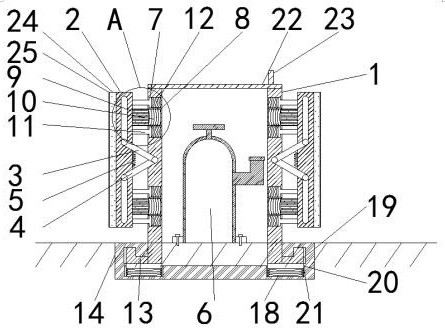
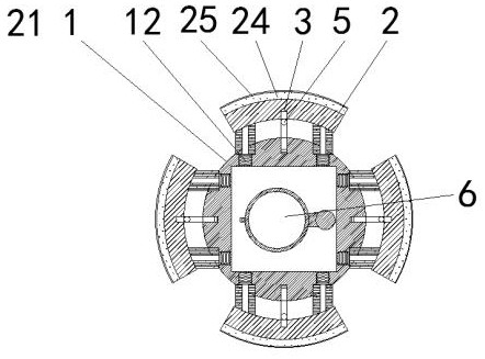
[0027] Example 1 see figure 1 According to an embodiment of the present invention, a safe fire hydrant with anti-collision effect includes a protective box 1, a protective plate 2 is provided on the four sides of the protective box 1, and elastic force is provided at the four corners of the protective plate 2 near the side of the protective box 1. Mechanism, the side of the protection plate 2 close to the protection box 1 is movably connected with the protection box 1 through the linkage rod 1 3 and the linkage rod 2 4, and the end of the linkage rod 3 and the linkage rod 2 4 away from the protection box 1 is slidingly connected with the protection plate 2 , A spring 5 is connected between the linkage rod 1 3 and the linkage rod 2 4, the protection box 1 is set on the outside of the fire hydrant body 6, and the bottom of the protection box 1 is provided with a loading and unloading mechanism.
Embodiment 2
[0028] Embodiment 2 Please refer to on the basis of embodiment 1 figure 1 , the elastic mechanism includes chute 7, square groove 8, movable block 9, spring two 10, T-shaped bar 11 and spring three 12, and the position of protection box 1 close to the four corners of protective plate 2 has two chute 7, chute 7 There is a square groove 8 between them, and the protective plate 2 is fixedly connected with a movable block 9, and the end of the movable block 9 away from the protective plate 2 is slidably connected with the square groove 8, and a spring two 10 is arranged between the square groove 8 and the movable block 9, and the movable Both sides above and below the block 9 are respectively provided with a T-shaped bar 11, one end of the T-shaped bar 11 is fixedly connected with the protective plate 2, the other end of the T-shaped bar 11 runs through the protection box 1 and is positioned in the chute 7, and the T-shaped bar 11 Slidingly connected with the chute 7, the chute 7 ...
Embodiment 3
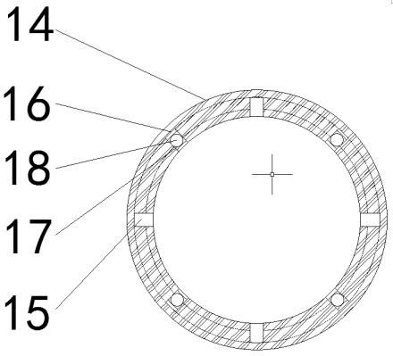
[0029] Embodiment 3 Please refer to on the basis of embodiment 1 figure 1 The loading and unloading mechanism includes an L-shaped slider 13, an annular chute 14, a notch 15, a groove 16, a fixed groove 17, a spring four 18, an annular slider 19, a limit slider 20 and a limit groove 21, and the protection box 1 The outer surface of the bottom of the bottom is uniformly fixedly connected with four L-shaped sliders 13, the bottom of the protection box 1 is provided with an annular chute 14 that is compatible with the L-shaped slider 13, and the top of the annular chute 14 is provided with an L-shaped chute. The notch 15 that is suitable for the L-shaped slider 13, the top of the annular chute 14 has a groove 16 that is compatible with the L-shaped slider 13, the groove 16 is interlaced with the notch 15, and the bottom of the annular chute 14 is provided with Fixed groove 17, fixed groove 17 is provided with spring four 18, and the top of spring four 18 is provided with annular ...
PUM
 Abstract
Description
Claims
Application Information
 - R&D
- Intellectual Property
- Life Sciences
- Materials
- Tech Scout
- Unparalleled Data Quality
- Higher Quality Content
- 60% Fewer Hallucinations
Browse by: Latest US Patents, China's latest patents, Technical Efficacy Thesaurus, Application Domain, Technology Topic, Popular Technical Reports.
© 2025 PatSnap. All rights reserved.Legal|Privacy policy|Modern Slavery Act Transparency Statement|Sitemap|About US| Contact US: help@patsnap.com