Hydraulic anti-loosening bolt and hydraulic anti-loosening bolt and nut fastening device
A fastening device and anti-loosening technology, applied in the direction of threaded fasteners, bolts, nuts, etc., can solve the problems of loosening of nuts and bolts, affecting work efficiency, waste, etc.
- Summary
- Abstract
- Description
- Claims
- Application Information
AI Technical Summary
Problems solved by technology
Method used
Image
Examples
Embodiment 1
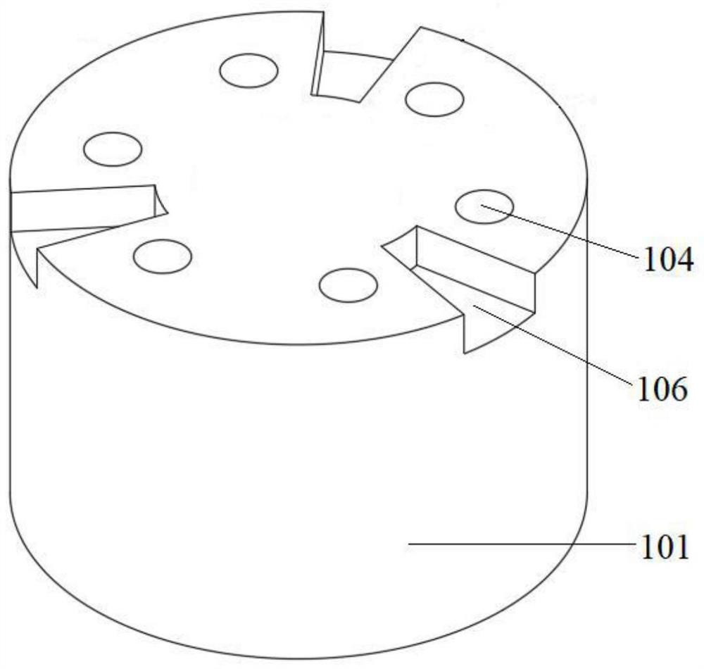
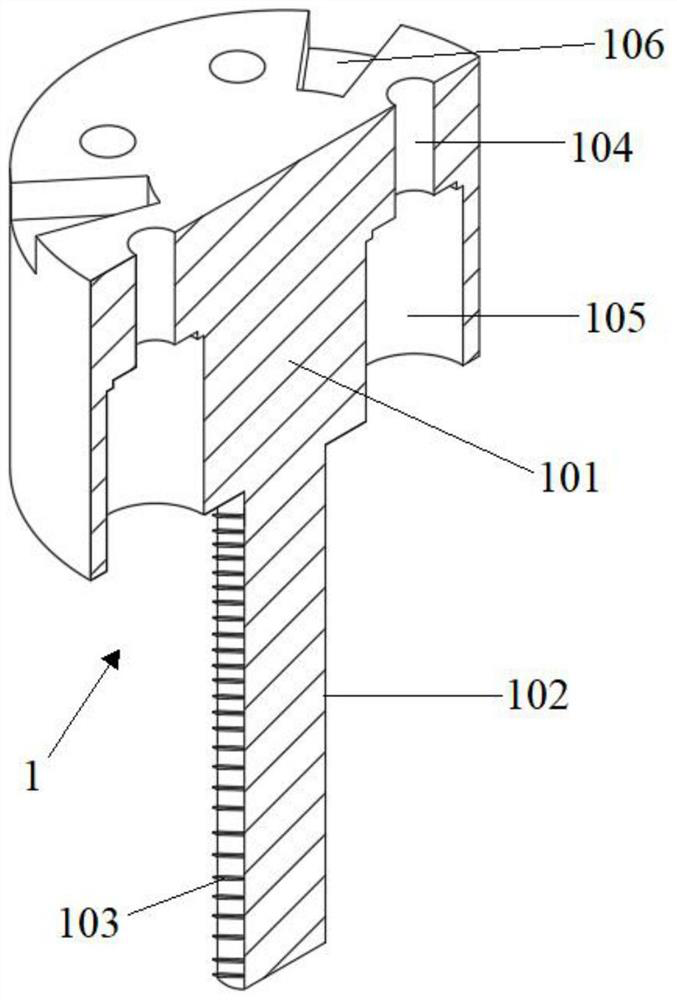
[0088] Such as figure 2 As shown, a hydraulic anti-loose loose bolt includes a nut 101, a screw 102, an outer thread 103. The nut 101 is disposed on the screw 102. The outer thread 103 is disposed on the outer surface of the screw 102. The anti-loose bolt 1 also includes a through hole 104 and a receiving chamber 105. The through hole 104 is opened on the upper surface of the nut 101. The accommodating chamber 105 is opened at the lower surface of the nut 101. The bottom end of the through hole 104 is in communication with the top end of the accommodating chamber 105. The through hole 104, the accommodating chamber 105 is located in a nut 101 between the outer wall of the screw 102 and the outer wall of the nut 101. Hydraulic anti-pore system 2 is also provided in the accommodating cavity 105.
Embodiment 2
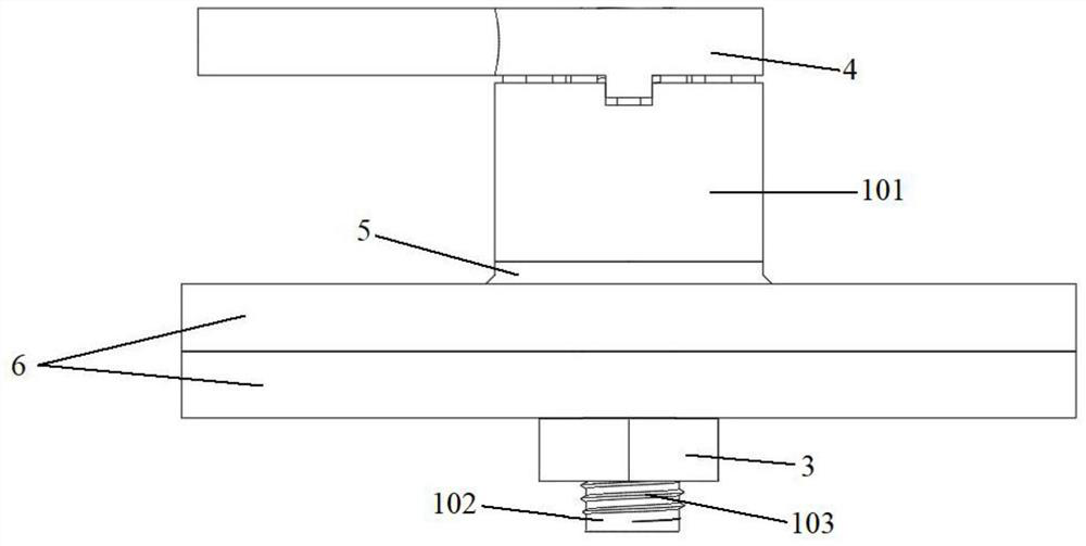
[0090] Such as figure 1 As shown, a hydraulic anti-loosening bolt, a nut fastening device, which includes a procedure bolt 1 and a nut 3. The anti-loosening bolt 1 is assembled with the nut 3 through the outer thread 103. The anti-loose bolt 1 includes a nut 101, a screw 102, an external thread 103. The nut 101 is disposed on the screw 102. The outer thread 103 is disposed on the outer surface of the screw 102. The nut 3 includes a nut body 301, a threaded hole 302, and an internal thread 303. The threaded hole 302 is disposed on the nut body 301. The internal thread 303 is disposed on the inner wall of the threaded hole 302. The anti-loose bolt 1 also includes a through hole 104 and a receiving chamber 105. The through hole 104 is opened on the upper surface of the nut 101. The accommodating chamber 105 is opened at the lower surface of the nut 101. The bottom end of the through hole 104 is in communication with the top end of the accommodating chamber 105. The through hole 104,...
Embodiment 3
[0092] Such as Figure 4 As shown, Embodiment 2 is repeated, except that the hydraulic anti-pillar system 2 includes a housing 201, an inner casing 202, a pressing device 203, a pin shaft 204, and an elastic member 205. The inner casing 202, and the pressing device 203 are each disposed in the inner cavity of the outer casing 201, and the pressing device 203 is set to the upper portion of the inner casing 202. The pin shaft 204, the elastic member 205 is provided in the inner cavity of the inner casing 202, and the elastic member 205 is located above the top end of the pin shaft 204.
PUM
 Abstract
Description
Claims
Application Information
 - R&D
- Intellectual Property
- Life Sciences
- Materials
- Tech Scout
- Unparalleled Data Quality
- Higher Quality Content
- 60% Fewer Hallucinations
Browse by: Latest US Patents, China's latest patents, Technical Efficacy Thesaurus, Application Domain, Technology Topic, Popular Technical Reports.
© 2025 PatSnap. All rights reserved.Legal|Privacy policy|Modern Slavery Act Transparency Statement|Sitemap|About US| Contact US: help@patsnap.com


