
Imaging lens

An imaging lens and lens technology, which is applied in the field of imaging lenses, can solve the problems that imaging lenses cannot satisfy large aperture, high resolution and resistance to environmental temperature changes at the same time, and achieve good optical performance, high resolution, and improved resolution.

Active Publication Date: 2021-03-09
SINTAI OPTICAL SHENZHEN CO LTD +1
View PDF6 Cites 1 Cited by
  • Summary
  • Abstract
  • Description
  • Claims
  • Application Information

AI Technical Summary

Problems solved by technology

[0003] The technical problem to be solved by the present invention is to provide an imaging lens with a smaller aperture value and a higher resolution in view of the defects that the imaging lens in the prior art cannot simultaneously meet the requirements of large aperture, high resolution and resistance to environmental temperature changes. High, resistant to ambient temperature changes, but still has good optical properties

Method used


Image

  • Imaging lens
  • Imaging lens
  • Imaging lens

Examples


Embodiment Construction

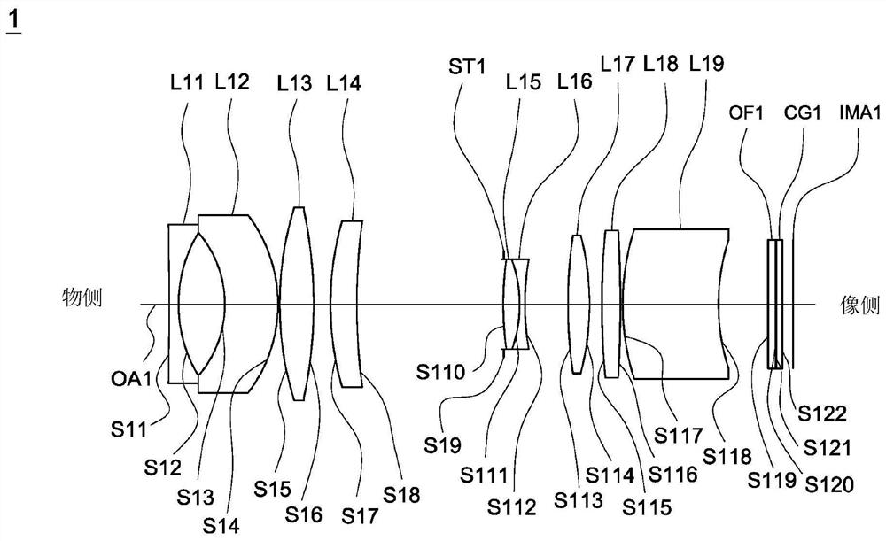
[0028] The invention provides an imaging lens, comprising: a first lens with negative refractive power, the first lens including a concave surface facing the image side; the second lens with negative refractive power; the third lens with positive refractive power; the fourth lens with positive refractive power; The fifth lens has positive refractive power; the sixth lens has negative refractive power; the seventh lens has refractive power; the eighth lens has refractive power; side; wherein the first lens, the second lens, the third lens, the fourth lens, the fifth lens, the sixth lens, the seventh lens, the eighth lens and the ninth lens are in sequence from the object side to the image side along the optical axis arrangement.

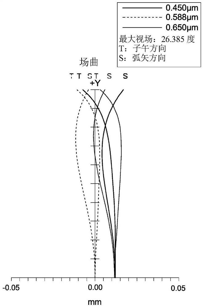
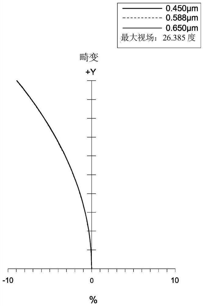
[0029] Please refer to Table 1, Table 3, Table 4, Table 6 and Table 7 below, wherein Table 1, Table 3 and Table 6 are the correlation of each lens of the first embodiment to the third embodiment of the imaging lens according to the present invention, ...


PUM


Abstract

An imaging lens comprises a first lens, a second lens, a third lens, a fourth lens, a fifth lens, a sixth lens, a seventh lens, an eighth lens and a ninth lens. The first lens has negative refractivepower and includes a concave surface facing the image side. The second lens has negative refractive power. The third lens has positive refractive power. The fourth lens has positive refractive power.The fifth lens has positive refractive power. The sixth lens has negative refractive power. The seventh lens has refractive power. The eighth lens has refractive power. The ninth lens is a meniscus lens and comprises a convex surface facing the object side and a concave surface facing the image side. The first lens, the second lens, the third lens, the fourth lens, the fifth lens, the sixth lens,the seventh lens, the eighth lens and the ninth lens are sequentially arranged from the object side to the image side.

Description

technical field [0001] The present invention relates to an imaging lens. Background technique [0002] The development trend of today's imaging lenses, in addition to the continuous development of large aperture and high resolution, requires the ability to resist environmental temperature changes with different application requirements. The known imaging lenses can no longer meet the current needs. There is another imaging lens with a new architecture to meet the needs of large aperture, high resolution and resistance to ambient temperature changes at the same time. SUMMARY OF THE INVENTION [0003] The technical problem to be solved by the present invention is to provide an imaging lens with a smaller aperture value and higher resolution in view of the defect that the imaging lens in the prior art cannot simultaneously meet the requirements of large aperture, high resolution and resistance to changes in ambient temperature. High, resistant to ambient temperature changes,...

Claims


Application Information

Patent Timeline
Patent Type & Authority Applications(China)
IPC IPC(8): G02B13/00G02B13/18
CPCG02B13/0045G02B13/006
Inventor 张安凯
Owner SINTAI OPTICAL SHENZHEN CO LTD
Learn More