
A Two-way Coupling Circuit Based on Orthogonal Field

A bidirectional coupling and orthogonal field technology, applied in the direction of circuits, electrical components, waveguide devices, etc., can solve the problems that traditional coupling circuits cannot adapt to miniaturized integration, bidirectional coupling, and large circuit size, and achieve miniaturized circuit integration , Solve the effect of two-way coupling detection

Active Publication Date: 2021-10-15
SOUTHWEST CHINA RES INST OF ELECTRONICS EQUIP
View PDF6 Cites 0 Cited by
  • Summary
  • Abstract
  • Description
  • Claims
  • Application Information

AI Technical Summary

Problems solved by technology

Another disadvantage is that the circuit size is large, such as figure 1 The length dimension L is related to the working frequency, especially in the case of two-way coupling applications, it is necessary to use two couplers to switch between active devices.
[0004] Traditional coupling circuits cannot meet the application requirements of miniaturized integration and bidirectional coupling, especially in the case of transceiver system applications, so there is an urgent need for new structural forms and methods to realize miniaturized bidirectional coupling circuits

Method used


Image

  • A Two-way Coupling Circuit Based on Orthogonal Field
  • A Two-way Coupling Circuit Based on Orthogonal Field
  • A Two-way Coupling Circuit Based on Orthogonal Field

Examples


Embodiment 1

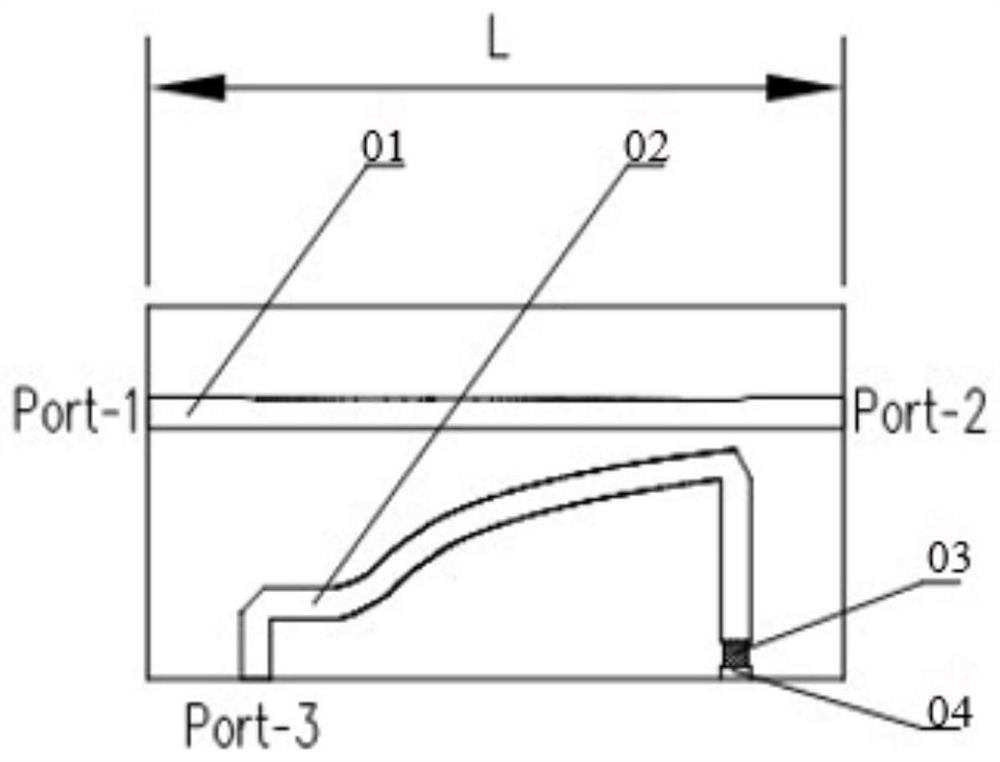
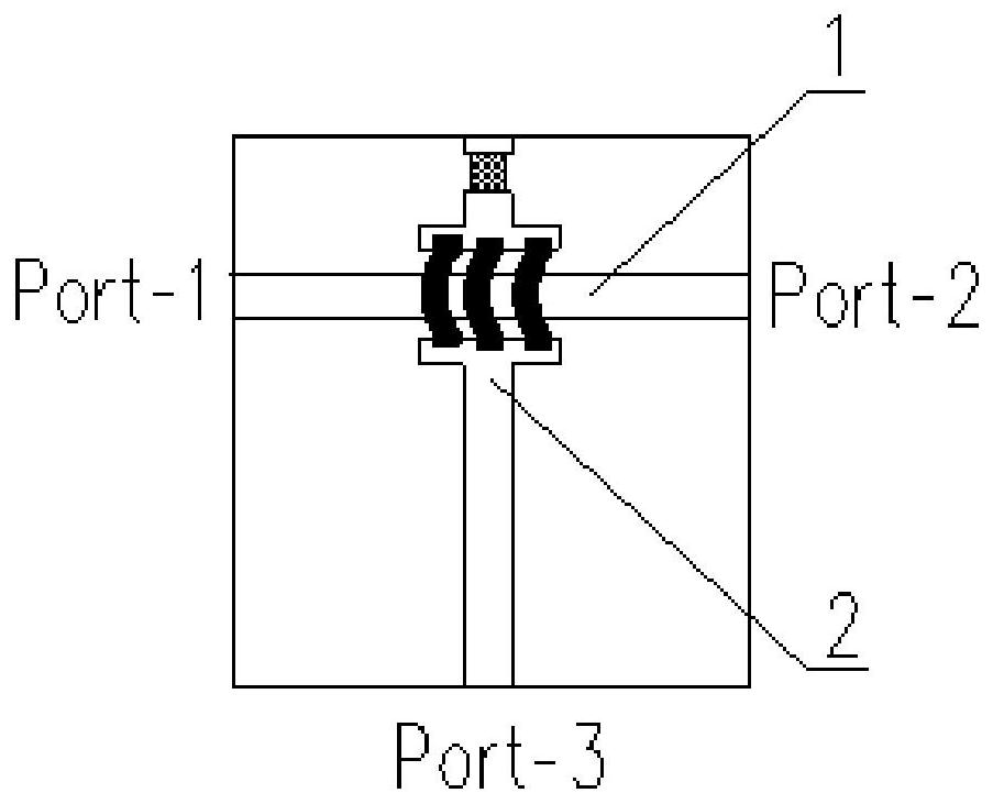
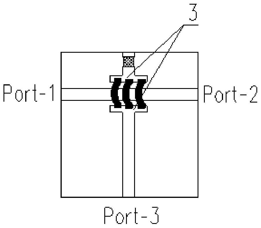
[0030] refer to Figure 2 to Figure 4 As shown, the invention discloses a bidirectional coupling circuit based on an orthogonal field. The bidirectional coupling circuit includes a main transmission line 1 , a coupling transmission line 2 , a coupling matching 3 , a matching resistor 4 and a gold strip 6 .

[0031] Wherein, the main transmission line 1 is a radio frequency signal microstrip transmission line, which realizes bidirectional signal transmission from port 1 to port 2 . The coupling transmission line 2 is a coupling signal microstrip transmission line, which realizes coupling signal extraction.

[0032] Preferably, the main transmission line 1 and the coupling transmission line 2 are arranged at 90°. The end of the coupled transmission line 2 is connected to the gold strip 6 via a coupling match 3 . The gold strip 6 crosses the main transmission line 1 and connects with the ground pad 5 on the dielectric substrate through the coupling matching 3 and the matching ...


PUM


Abstract

The invention discloses a two-way coupling circuit based on an orthogonal field. The two-way coupling circuit includes a main transmission line, a coupling transmission line, a coupling matching, a matching resistor and a gold band, wherein the main transmission line and the coupling transmission line are arranged at 90°, The end of the coupling transmission line is connected to the gold strip through coupling matching, and the gold strip crosses the main transmission line and is connected to the ground pad on the dielectric substrate through coupling matching and matching resistance; Port 1 to Port 3 and Port 2 are formed Symmetrical coupling circuit to port 3. The circuit design structure of two-way coupling of transmission and reception is realized through the orthogonal field. Compared with other existing technologies, the existing coupling circuit cannot realize the effective coupling of two-way transmission signals. The coupling circuit invented by this patent does not occupy additional circuit size, which is the realization of The circuit is miniaturized and integrated, and it is a good solution to solve the two-way coupling detection of the transceiver system.

Description

technical field [0001] The invention belongs to the field of radio frequency microwave circuit design, in particular to coupling circuit design. Background technique [0002] In the design of RF microwave circuits, coupling circuits are very common. Usually, coupling circuits are used to extract signal parameters for self-test / self-calibration of microwave channels. [0003] The traditional coupling circuit is the broadside coupling mode of the microstrip line (such as figure 1 As shown), this coupling circuit is easy to achieve broadband coupling characteristics, but it can only achieve coupling extraction in one signal direction, that is, the coupling is directional. The signal transmission direction is: Port1-Port2, and the coupling direction is: Port1-Port3. Another disadvantage is that the circuit size is large, such as figure 1 The length dimension L is related to the working frequency, especially in the case of two-way coupling applications, it is necessary to use...

Claims


Application Information

Patent Timeline
Patent Type & Authority Patents(China)
IPC IPC(8): H01P5/18
CPCH01P5/18
Inventor 彭文超罗明卢子焱蔡雪芳周义
Owner SOUTHWEST CHINA RES INST OF ELECTRONICS EQUIP
Learn More