New energy charging gun convenient to carry

A charging gun and new energy technology, applied in charging stations, electric vehicle charging technology, circuits, etc., can solve the problems of high energy consumption, loose touch or unplugged intentionally by others, and cumbersome structure and operation process, etc., to achieve Easy to take and store, increase anti-theft performance, and avoid the effect of being stolen and lost

Inactive Publication Date: 2021-03-09
杨益
View PDF1 Cites 3 Cited by
  • Summary
  • Abstract
  • Description
  • Claims
  • Application Information

AI Technical Summary

Problems solved by technology

[0003] The current patent number is CN107399246B, which discloses a new energy vehicle charging device, which drives the sliding block to slide to the left by making the motor work and rotate, so that the outer end faces of the two sliding frames are in contact with the outer end walls of the corresponding sliding grooves, The locking bar is about to be unlocked, and the motor is controlled to work in reverse, so that the sliding block is retracted into the telescopic slot, so that it can be restored to the initial position, so that the charging gun can be inserted next time. Although this solution makes the charging gun convenient to use, but Because the structure and operation process is too cumbersome, for users who are not familiar with the operation process, it takes a lot of energy to get familiar with the process, and this type of charging gun has a large instability factor when charging the car, especially for household and public use. When the charging pile is charging, it is often loosened by others unintentional touch or unplugged intentionally by others to use for their own vehicles

Method used


Image

  • New energy charging gun convenient to carry
  • New energy charging gun convenient to carry
  • New energy charging gun convenient to carry

Examples


Embodiment Construction

[0031] The following will clearly and completely describe the technical solutions in the embodiments of the present invention in conjunction with the accompanying drawings in the embodiments of the present invention. Obviously, the described embodiments are only some of the embodiments of the present invention, not all of them.

[0032] as attached figure 1 to attach Figure 8 Shown:

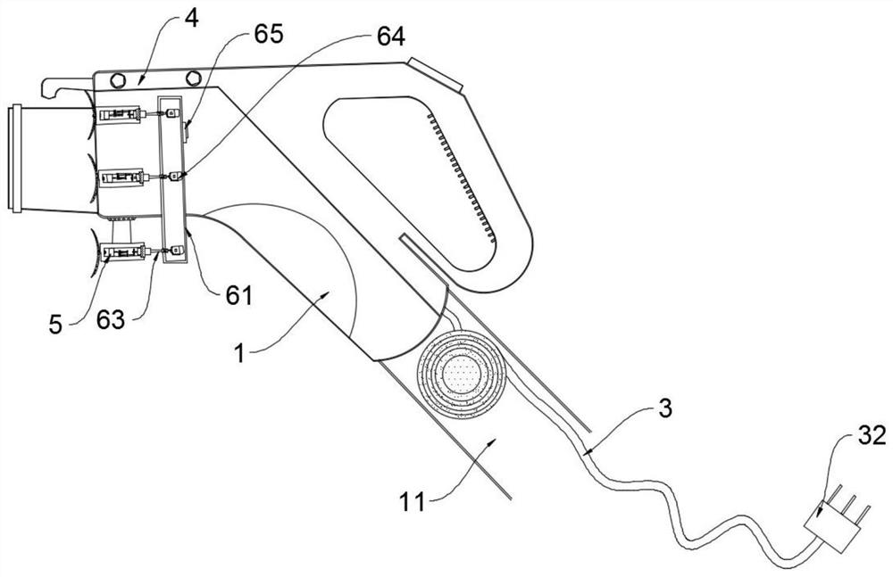
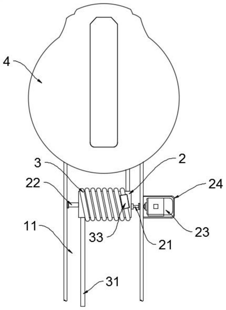
[0033] The present invention provides a portable new energy charging gun, which includes a gun handle 1, a winding cavity 11 is opened at the bottom of the gun handle 1, the winding cavity 11 communicates with the outside world, and a winding wheel 2 is arranged in the winding cavity 11. Both sides of the wire wheel 2 are respectively provided with a driving shaft 21 and a driven shaft 22, one end of the driven shaft 22 is connected to the side of the winding wheel 2 in rotation, and the end of the driven shaft 22 away from the winding wheel 2 passes through the inner wall of the winding chambe...


PUM


Abstract

The invention discloses a new energy charging gun convenient to carry. When the new energy charging gun convenient to carry by hand is used, a charging socket is connected with a charging pile, then awinding motor is driven, the winding motor adopts a positive and negative rotation gear motor, and the winding motor drives a winding wheel to rotate, so that the movable end of an electric wire extends, and a user can use the charging gun conveniently; the household charging pile is generally installed in an underground parking lot of a community, a charging gun placed in the parking lot has therisk of being stolen and lost, when the charging gun is not used, a user can separate a charging socket in the charging gun from a charging pile body, then a winding motor drives a winding wheel to rotate, and an electric wire is contracted, wound and stored, so that the user can take and store the charging gun conveniently, and the charging gun is effectively prevented from being stolen and lost; the multiple suction cups can be adsorbed to the surface of an automobile in a negative pressure mode, large adsorption force is generated on the surface, the charging gun is stabilized on a charging interface of the automobile, the charging gun is not prone to being touched by other people to loosen or fall off, and the anti-theft performance is improved.

Description

technical field [0001] The invention relates to the field of new energy technology, in particular to a portable new energy charging gun. Background technique [0002] The electric vehicle charging gun is mainly used for charging electric vehicles. The charging gun acts as the interface between the charging equipment and the rechargeable battery of the electric vehicle. The country has mandatory standards. All charging piles and electric vehicle manufacturers must abide by them to ensure The connection consistency with the gun, the charging gun is divided into seven connectors (AC pile) and nine connectors (DC pile), each connector represents a different power supply or control signal, the specific national standard has regulations, the charging gun is not only connected to the electric Cars and charging piles are also tied to the convenience of users when charging. As an excellent charging gun company, it is necessary not only to make charging guns with good charging perform...

Claims


Application Information

Patent Timeline
Patent Type & Authority Applications(China)
IPC IPC(8): H01R13/72H01R13/639H01R31/06B60L53/16
CPCB60L53/16H01R13/639H01R13/72H01R31/06H01R2201/26Y02T10/70Y02T10/7072Y02T90/14
Inventor 杨益
Owner 杨益
Why Eureka
Try Eureka