Time data recording method, device and apparatus

A technology of time data and recording method, applied in the Internet field, can solve the problem of inability to obtain accurate data transmission time and so on

Pending Publication Date: 2021-03-09
ALIBABA GRP HLDG LTD
View PDF0 Cites 0 Cited by
  • Summary
  • Abstract
  • Description
  • Claims
  • Application Information

AI Technical Summary

Problems solved by technology

To sum up, if the sending end and the receiving end cannot be accurately synchronized, the accurate data transmission time cannot be obtained

Method used


Image

  • Time data recording method, device and apparatus
  • Time data recording method, device and apparatus
  • Time data recording method, device and apparatus

Examples


Embodiment 1

[0078] Embodiment 1: The embodiment of this application proposes a time data recording method, which can be applied to any device, such as a time data recording device, without limitation, such as a sending end, a receiving end, or other types of devices. see image 3 Shown is a schematic flow chart of the method, and the method may include:

[0079] Step 301, obtain the data transmission time, and obtain the optimal transmission time; wherein, the optimal transmission time is the minimum data transmission time among all data transmission times before the current moment.

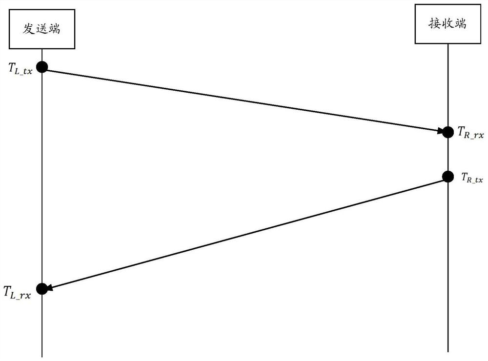
[0080] In one example, if the data transmission time is the request transmission time of the request message from the sender to the receiver, the first moment when the sender sends out the request message and the second moment when the receiver receives the request message are obtained, and based on the first Moment and the second moment get the request transmission time. For example, the first moment when...

Embodiment 2

[0099] Embodiment 2: Based on the same application concept as the above method, a method for recording time data is proposed in the embodiment of this application, see Figure 4 Shown is a schematic flow chart of the method, and the method may include:

[0100] Step 401, obtain the data transmission time, and obtain the optimal transmission time; wherein, the optimal transmission time is the minimum data transmission time among all the data transmission times before the current moment.

[0101] Step 402, judging whether the data transmission time is less than the optimal transmission time.

[0102] If yes, step 403 may be performed, and if no, step 404 may be performed.

[0103] Step 403, updating the data transmission time to an optimal transmission time.

[0104] After step 403, step 404 is executed based on the updated optimal transmission time.

[0105] Step 404, determine the difference between the data transmission time and the optimal transmission time (that is, the ...

Embodiment 3

[0109] Embodiment 3: Based on the same application concept as the above method, a method for recording time data is proposed in the embodiment of this application, see Figure 5 Shown is a schematic flow chart of the method, and the method may include:

[0110] Step 501, obtain data transmission time, and obtain an optimal transmission time; wherein, the optimal transmission time is the minimum data transmission time among all data transmission times before the current moment.

[0111] Step 502, if the current time has not reached the optimal aging period and the data transmission time is greater than or equal to the optimal transmission time, determine the difference between the data transmission time and the optimal transmission time.

[0112] Step 503, recording the difference between the data transmission time and the optimal transmission time in the tracking log.

[0113] Wherein, step 501-step 503 may refer to step 301-step 303, which will not be repeated here.

[0114...


PUM


Abstract

The invention provides a time data recording method, device and apparatus, and the method comprises the steps: obtaining the data transmission time, and obtaining the optimal transmission time, wherein the optimal transmission time is the minimum data transmission time in all data transmission time before the current moment; if the data transmission time is greater than or equal to the optimal transmission time, determining a difference value between the data transmission time and the optimal transmission time, the difference value being used for reflecting network transmission quality; and recording the difference value in a tracking log. Through the technical scheme of the invention, the network congestion condition can be accurately reflected based on the difference between the data transmission time and the optimal transmission time.

Description

technical field [0001] The present application relates to the Internet field, and in particular to a method, device and equipment for recording time data. Background technique [0002] During data transmission, the sending end sends a request message to the receiving end, and the receiving end returns a response message to the sending end for the request message. In order to collect time information, the sending end records the sending time of the request message, which is recorded as time 1; the receiving end records the receiving time of the request message, which is recorded as time 2; the receiving end records the sending time of the response message, which is recorded as time 3; the sending end records The receiving time of the response message is recorded as time 4. [0003] Obviously, the difference between time 2 and time 1 is the transmission time of the request message in the network, which is used to represent the data transmission time from the sender to the rec...

Claims


Application Information

Patent Timeline
Patent Type & Authority Applications(China)
IPC IPC(8): H04L12/26H04L12/801
CPCH04L43/08H04L47/11
Inventor 常怀鑫宋卓李靖轩
Owner ALIBABA GRP HLDG LTD
Why Eureka
Try Eureka