Thermal printer

A technology of thermal printers and print heads, applied in printing devices, printing, etc., can solve the problems of inconvenient reinstallation, difficult assembly, difficult control, etc., and achieve the effect of facilitating assembly and compact structure

Active Publication Date: 2021-03-12
宁波精芯科技有限公司
View PDF10 Cites 0 Cited by
  • Summary
  • Abstract
  • Description
  • Claims
  • Application Information

AI Technical Summary

Problems solved by technology

But there are the following disadvantages: the bearing moves in the shaft groove to a large extent, which affects the normal operation of the rubber roller
[0005] Further, the applicant has developed an improved structure, see the Chinese invention patent "Installation Structure of Rubber Roller Assembly" with the patent number ZL201710535434.5 (authorized announcement number is CN107284048B), the patent passes

Method used


Image

  • Thermal printer
  • Thermal printer
  • Thermal printer

Examples


Embodiment Construction

[0026] The present invention will be further described in detail below in conjunction with the accompanying drawings and embodiments.

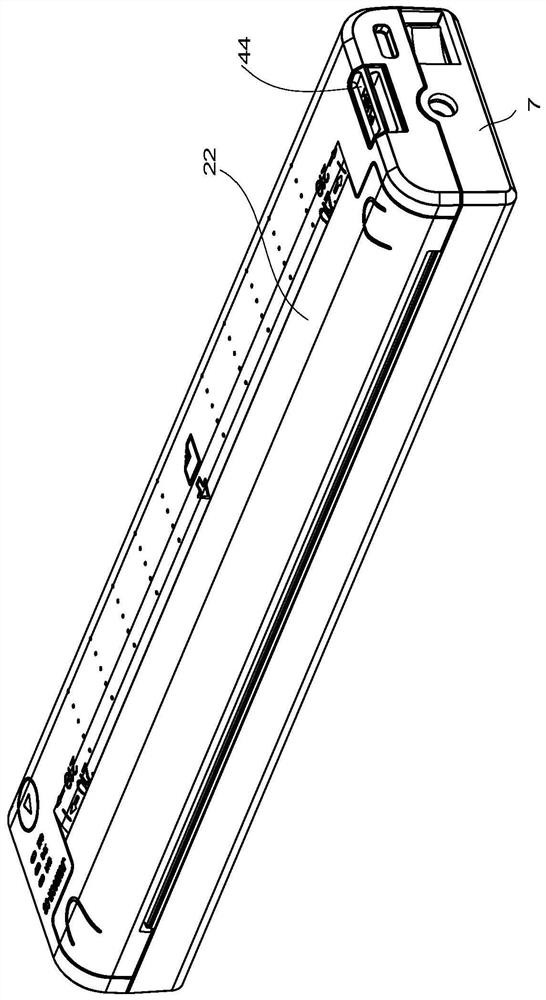
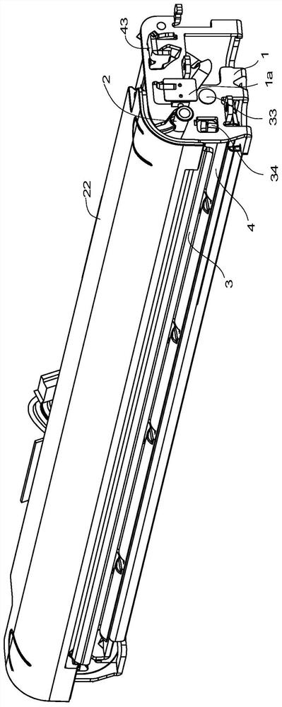
[0027] Such as figure 1 , image 3 , Figure 4 with Figure 5 As shown, the thermal printer in this embodiment includes a casing 7, a frame 1, a print head assembly 3, a rubber roller assembly 2, a motor 6 and a transmission gear set 61, the frame 1 is located in the casing 7, and the print head The assembly 3 is set on the frame 1, the rubber roller assembly 2 is rotatably arranged on the frame 1 and arranged close to the print head assembly 3, one end of the rubber roller assembly 2 is provided with an input gear 211, and the motor 6 is driven by a transmission gear set 61 Rubber roller assembly 2 rotates.

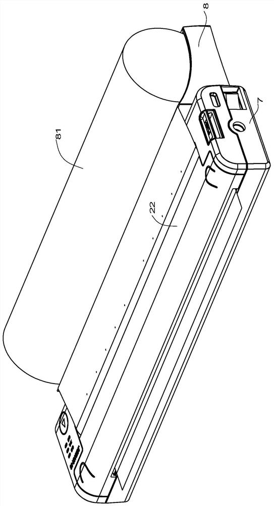
[0028] When it is necessary to print roll-shaped printing paper, the paper roll support 8 can be arranged on one side of the casing 7, such as figure 2 shown. When printing a single sheet of printing paper, the paper roll support ...


PUM


Abstract

A thermal printer comprises a casing, a rack, a printing head assembly, a rubber roller assembly, a motor and a transmission gear set, and is characterized in that shaft grooves allowing the two endsof the rubber roller assembly to be rotatably arranged are formed in two sides of the rack, and a rotating plate is rotatably arranged on the rack; the rotating plate comprises a connecting portion parallel to a printing head support and a swing portion at least arranged on one side of the connecting portion, and the swing portion is arranged close to the shaft grooves of the rack; and the connecting portion is located on one side of the printing head support, and an elastic part is arranged between the connecting portion and the back face of the printing head support and always forces a thermal printing head to be close to the rubber roller assembly. The connecting portion of the rotating plate replaces an original mounting plate for mounting the elastic part, meanwhile, resetting of therotating plate is achieved through the elastic part, the pressing design of the printing head assembly and resetting of the rotating plate are combined, the structure is more compact, and assembling is facilitated.

Description

technical field [0001] The invention relates to a printer device, in particular to a portable thermal printer. Background technique [0002] Existing thermal printers generally include a frame, a motor, a transmission gear assembly, a print head assembly, and a rubber roller that can be rotatably arranged on the frame. The power input end of the transmission gear assembly meshes with the active output gear of the motor, and the power output The end meshes with the rubber roller gear located at the end of the rubber roller. The rubber roller is used to drive the printing paper to move. There is a paper feeding channel between the rubber roller and the print head assembly. The print head assembly generally includes a print head (TPH for short, Thermal Print Head), print head bracket, compression spring and compression spring supporting frame, the printing head is arranged on the printing head bracket, and the two ends of the compression spring supporting frame are arranged at ...

Claims


Application Information

Patent Timeline
IPC IPC(8): B41J2/32B41J11/04
CPCB41J2/32B41J11/04
Inventor 蒋文柏
Owner 宁波精芯科技有限公司
Why Eureka
Try Eureka