
High-bearing airfoil joint load transferring structure

A high load-bearing and airfoil technology, applied in the fuselage frame, fuselage, transportation and packaging, etc., can solve the problems of loss of load-bearing capacity, effective transfer of airfoil structure, failure of connection interface structure, etc., to achieve the ultimate airfoil load-bearing capacity Effect

Active Publication Date: 2021-03-12
AEROSPACE INST OF ADVANCED MATERIALS & PROCESSING TECH
View PDF8 Cites 1 Cited by
  • Summary
  • Abstract
  • Description
  • Claims
  • Application Information

AI Technical Summary

Problems solved by technology

[0003] The traditional airfoil joint design mostly adopts the way of direct connection between the composite material girder structure and the metal joint. There is no effective force transmission path between the two, so that when the airfoil structure is subjected to aerodynamic load, the connection interface between the two will first experience structural failure. As a result, the overall airfoil structure cannot continue to bear the load in a relatively complete structural state
[0004] Therefore, how to solve the problem of premature failure of the airfoil structure and loss of bearing capacity due to the inability to realize the effective transfer of the airfoil load to the metal joint structure in the traditional metal joint and airfoil structure design is a problem that the relevant industry needs to research and develop urgently where the

Method used


Image

  • High-bearing airfoil joint load transferring structure
  • High-bearing airfoil joint load transferring structure
  • High-bearing airfoil joint load transferring structure

Examples


Embodiment Construction

[0023] In order to make the technical solution of the present invention more comprehensible, specific embodiments and accompanying drawings are described in detail as follows.

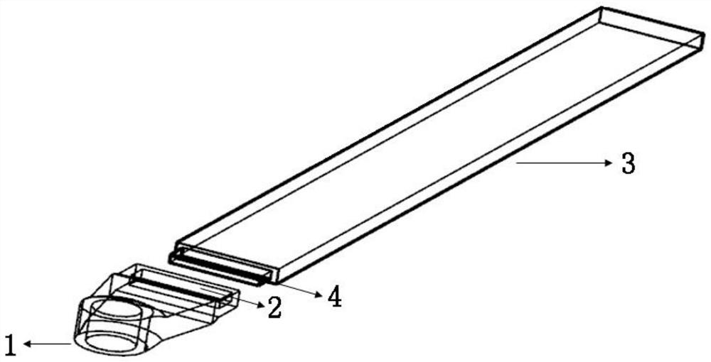
[0024] This embodiment discloses a load-carrying structure of a high-load airfoil joint, such as figure 1 As shown, it includes a metal joint 1 and a composite material girder 3, and the specific description is as follows.

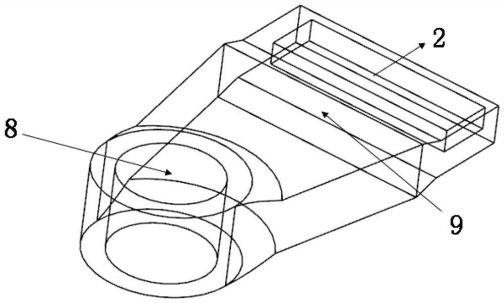
[0025] The metal joint 1 includes a fuselage connection interface 8 at one end and a girder connection surface at the other end, the girder connection surface contains a groove 2, and the structure is as follows figure 2 shown. One side of the metal joint 1 contains an airfoil connection area 9 . The thickness of the end where the fuselage connection interface 8 of the metal joint 1 is located is greater than the thickness of the end where the girder connection surface is located, so as to effectively increase the structural bending section coefficient and enhance the structural...


PUM


Abstract

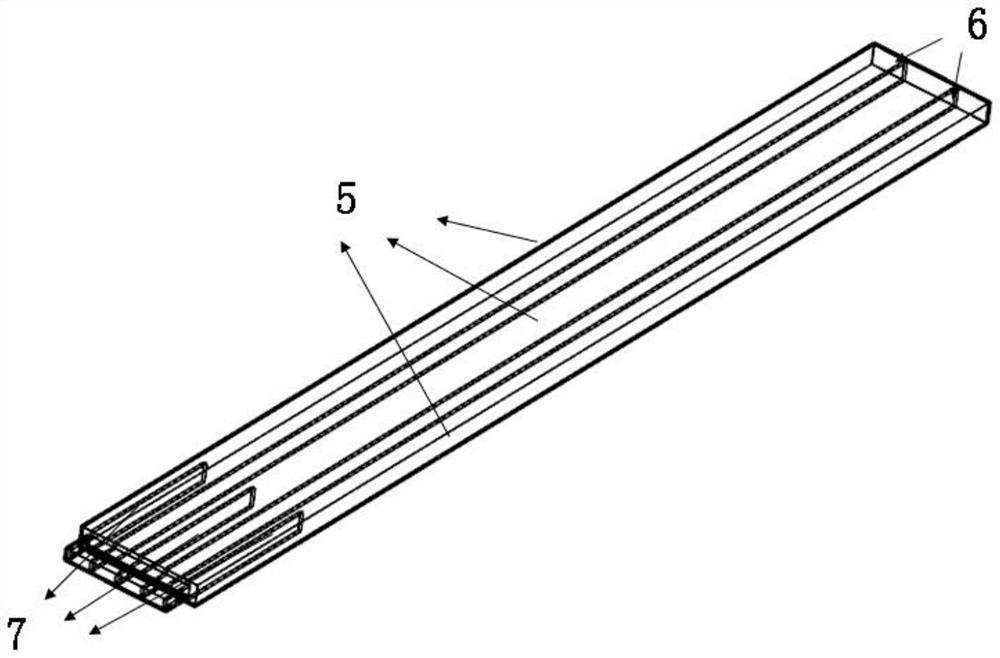
The invention discloses a high-bearing airfoil joint load transfer structure, which belongs to the field of application of carbon fiber composite materials, and comprises a metal joint and a compositematerial girder, wherein the metal joint comprises a fuselage connecting interface positioned at one end and a girder connecting surface positioned at the other end, and the girder connecting surfacecomprises a groove; the composite material girder comprises a plurality of sandwich structure beams and a plurality of long-strip-shaped composite material walls, the sandwich structure beams are adjacently connected side by side, any composite material wall is located between the two sandwich structure beams, and a metal sheet in the length direction of the sandwich structure beams is embedded in one end of each sandwich structure beam. The same ends of the sandwich structure beams, the metal sheet and the composite material walls are respectively provided with a protruding structure, the protruding structures jointly form a boss matched with the groove of the metal structure, and the composite material girder is inserted into the groove of the metal connector through the boss to be connected with the metal connector. Effective transmission of aircraft airfoil load to the metal joint structure can be realized, and loss of bearing capacity due to advanced failure of the airfoil structure is avoided.

Description

technical field [0001] The invention belongs to the application field of carbon fiber composite materials, and in particular relates to a high-load-bearing airfoil joint load-transfer structure. Background technique [0002] The carbon fiber composite airfoil structure can meet the lightweight requirements of the structure on the basis of realizing the flight lift requirements of the aircraft. In the composite airfoil structure, the connection form between the composite airfoil structure and the metal joint is an important factor restricting the ultimate bearing capacity of the airfoil. [0003] The traditional airfoil joint design mostly adopts the way of direct connection between the composite material girder structure and the metal joint. There is no effective force transmission path between the two, so that when the airfoil structure is subjected to aerodynamic load, the connection interface between the two will first experience structural failure. As a result, the over...

Claims


Application Information

Patent Timeline
IPC IPC(8): B64C1/00B64C1/06
CPCB64C1/00B64C1/069B64C2001/0072
Inventor 田智立龚文化张涛
Owner AEROSPACE INST OF ADVANCED MATERIALS & PROCESSING TECH
Learn More