
Flywheel resistance adjustment structure and exercise bike

A resistance adjustment and flywheel technology, applied in the field of fitness equipment, can solve problems such as large randomness of debugging results, unfavorable electric or automatic adjustment, easy jamming and blocking, etc., which is beneficial to cost and quality control, and reduces after-sales service costs. , The effect of improving the life of the flywheel

Inactive Publication Date: 2019-01-18
德尔康(上海)运动用品有限公司
View PDF9 Cites 2 Cited by
  • Summary
  • Abstract
  • Description
  • Claims
  • Application Information

AI Technical Summary

Problems solved by technology

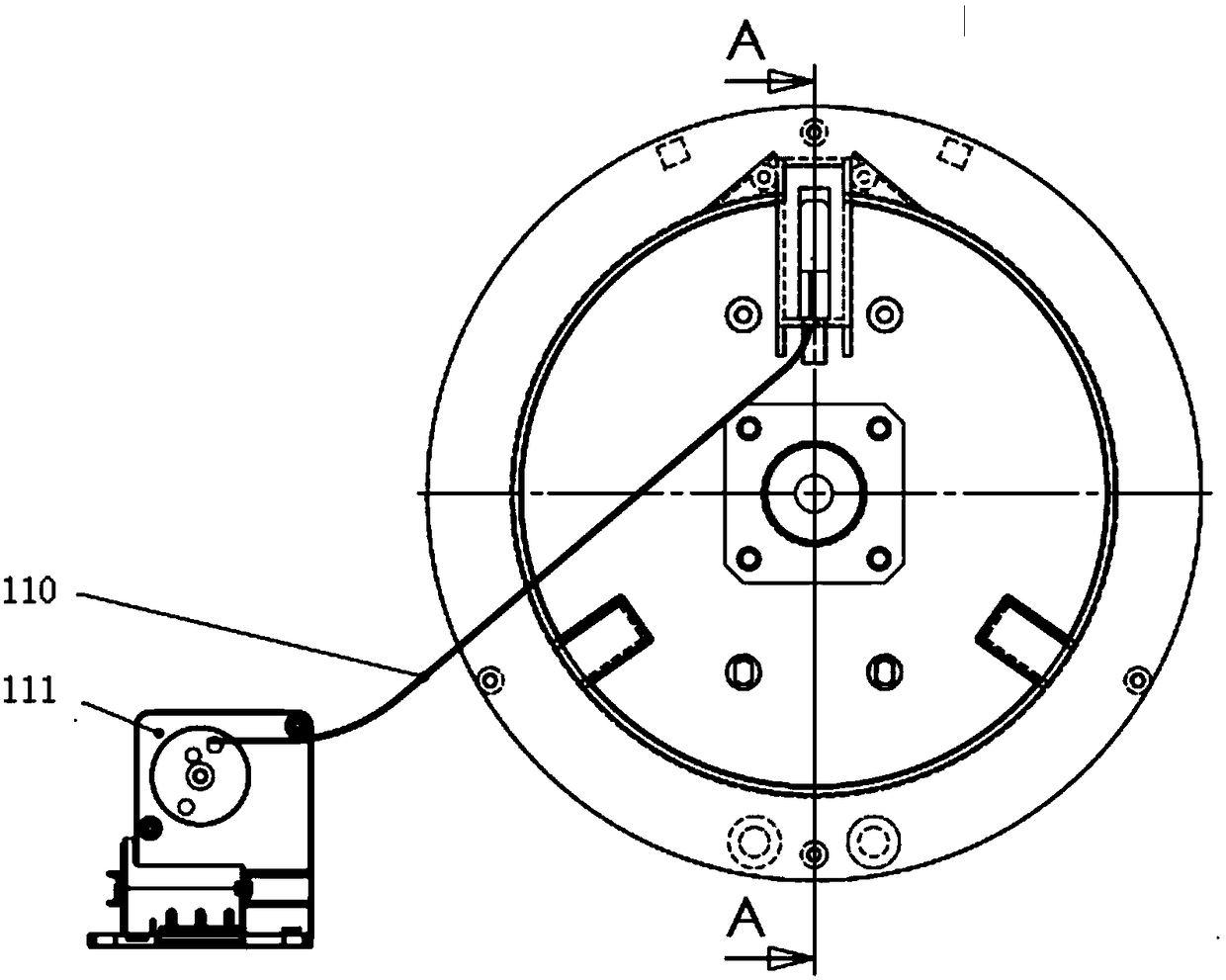
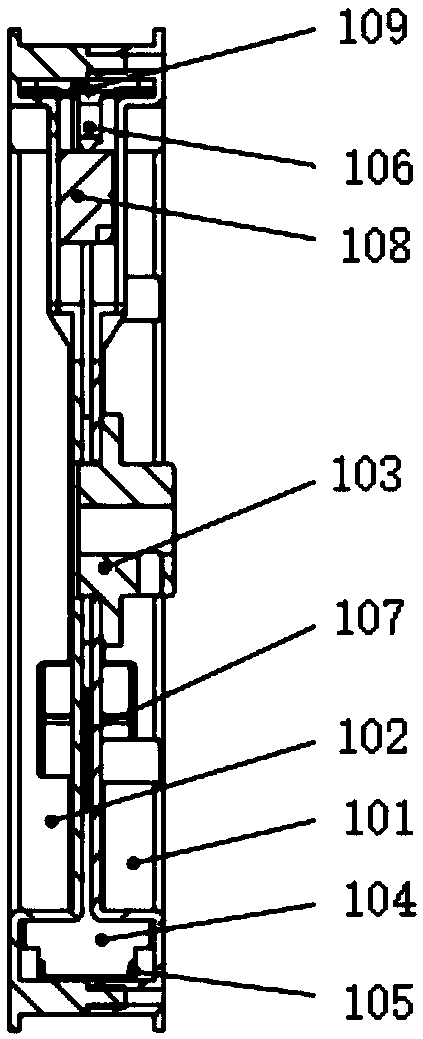
[0003] Disadvantages of the existing flywheel resistance adjustment structure: 1. Poor control accuracy; 2. Inconvenient installation, large randomness and poor consistency of debugging results; 3. Easy to get stuck and blocked; The gap adjustment between 104 and the metal rotating wheel is loosely connected by several parts, and there are various gaps, which lead to uncertainty in resistance adjustment and affect customer experience; 5. The life of the entire flywheel depends on the fatigue failure of these parts, due to the slippage Sliding friction between the block 108 and the slider chute directly leads to wear of the friction surface, so the life is short
[0004] The patent document CN 106730636A provides a convenient fitness equipment to adjust the distance between the magnet group and the flywheel by pulling the handle to achieve the purpose of adjusting the resistance, but this structure is suitable for manual operation, and it is difficult to adapt to the motor-driven structure, which is not conducive to electric or auto adjust
Patent document CN202620563U provides a flywheel device for exercise bikes, which can adjust the resistance of the flywheel by controlling the current in the electromagnet, but requires additional configuration of the electromagnet structure and related circuits, which increases the difficulty of manufacturing
In the magnetic resistance mechanism in the cable equipment provided by the patent document CN105848733B, the resistance mechanism includes a flywheel and a magnetic unit arranged to resist the movement of the flywheel, but this moving structure is not suitable for applications such as exercise bikes with small space and compact structure

Method used


Image

  • Flywheel resistance adjustment structure and exercise bike
  • Flywheel resistance adjustment structure and exercise bike
  • Flywheel resistance adjustment structure and exercise bike

Examples


Embodiment Construction

[0042] The present invention will be described in detail below in conjunction with specific embodiments. The following examples will help those skilled in the art to further understand the present invention, but do not limit the present invention in any form. It should be noted that those skilled in the art can make several modifications and improvements without departing from the concept of the present invention. These all belong to the protection scope of the present invention.

[0043] In describing the present invention, it is to be understood that the terms "upper", "lower", "front", "rear", "left", "right", "vertical", "horizontal", "top", The orientation or positional relationship indicated by "bottom", "inner", "outer", etc. is based on the orientation or positional relationship shown in the drawings, and is only for the convenience of describing the present invention and simplifying the description, rather than indicating or implying the referred device Or elements ...


PUM


Abstract

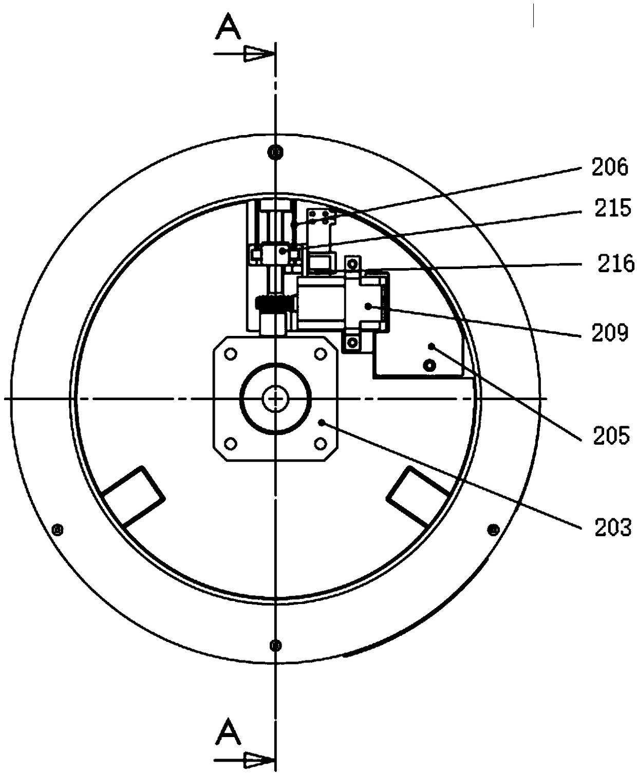
The invention provides a flywheel resistance adjusting structure, comprising a flywheel, an electric motor (210), a transmission structure and a magnetic tile (204). An electric motor (210), a transmission structure and a magnetic bush (204) are mounted on the flywheel; The transmission structure comprises a speed reduction assembly, a lead screw assembly, a motor (210), a speed reduction assembly, a lead screw assembly and a magnetic tile (204), wherein the magnetic tile (204) is slidably mounted on a flywheel; The screw assembly comprises a screw rod (213) and an adjusting nut; A lead screwassembly is arrange in any one of that following way: a screw rod (213) is connected to the speed reduction assembly, an adjusting nut is connected to a magnetic tile (204); The adjusting nut is connected to the speed reduction assembly, and the screw rod (213) is connected to the magnetic tile (204). The invention also provides an exercise bicycle comprising the flywheel resistance adjusting structure. The invention saves the external cable, the extra position of the external cable motor is fixed, and various intermediate connecting parts are favorable for environmental protection and cost control.

Description

technical field [0001] The invention relates to the field of fitness equipment and the technical field of electromagnetic adjustment, in particular to a flywheel resistance adjustment structure and an exercise bike. Background technique [0002] Please refer to the existing flywheel resistance adjustment structure figure 1 and figure 2 , mainly by short steel wire stay rope 109, long steel wire stay rope 110, stay rope slider 108, slider chute, external tension generating structure, magnetic tile 104, metal rotating wheel and form. The external pulling force comes from the deceleration motor 111 installed on the outside, and is connected to the stay rope slider 108 through the long steel wire stay rope 110. When the pulling force of the deceleration motor 111 acts, the stay rope slider 108 just slides up and down in the slider chute, The magnetic tile 104 is driven to move by the short steel wire stay rope 109, and the size of the gap between the magnetic tile 104 and the...

Claims


Application Information

Patent Timeline
Patent Type & Authority Applications(China)
IPC IPC(8): A63B22/08A63B21/005
CPCA63B21/0058A63B22/0605
Inventor 乔同舟
Owner 德尔康(上海)运动用品有限公司
Learn More