Engineering machinery and engineering machinery control method

A technology for construction machinery and controllers, applied in mechanical equipment, cranes, transportation and packaging, etc., can solve problems such as container collision, engine aging, and reduced engine working life, so as to reduce sealing requirements, reduce use costs, and reduce control cost effect

Active Publication Date: 2009-05-27
SANY MARINE HEAVY IND +1
View PDF0 Cites 30 Cited by
  • Summary
  • Abstract
  • Description
  • Claims
  • Application Information

AI Technical Summary

Problems solved by technology

The frequent adjustment of the engine output speed according to the load change will easily cause the corresponding parts of the engine to age in advance, affect the power performance of the engine, and reduce the working life of the engine; and frequent adjustment of the engine output speed is not conducive to reducing fuel consumption
[0005] In addition, the existing technology is not conducive to the micro-adjustment of the hydraulic actuator
Taking the container reach stacker as an example, when it is necessary to fine-tune the position of the spreader or the container, since the output speed of the engine increases with the increase of the adjustment range of the operating handle, it is easy to cause corresponding vibrations due to the impact of high-pressure oil when the boom is started. The impact action makes it difficult to realize the micro-adjustment of the spreader. It needs multiple and repeated adjustments to make the spreader or the container reach the predetermined position, which reduces the efficiency of the container reach stacker lifting operation
Impact actions of high-pressure oil or repeated position adjustments can also easily cause containers to collide with each other
[0006] Those skilled in the art can understand that in other construction machinery using the prior art, such as when accurately adjusting the position of the discharge port of the concrete pump truck, the same problem also exists. It is very difficult to accurately locate the corresponding position after completing the micro-adjustment

Method used


Image

  • Engineering machinery and engineering machinery control method
  • Engineering machinery and engineering machinery control method
  • Engineering machinery and engineering machinery control method

Examples


Embodiment 1

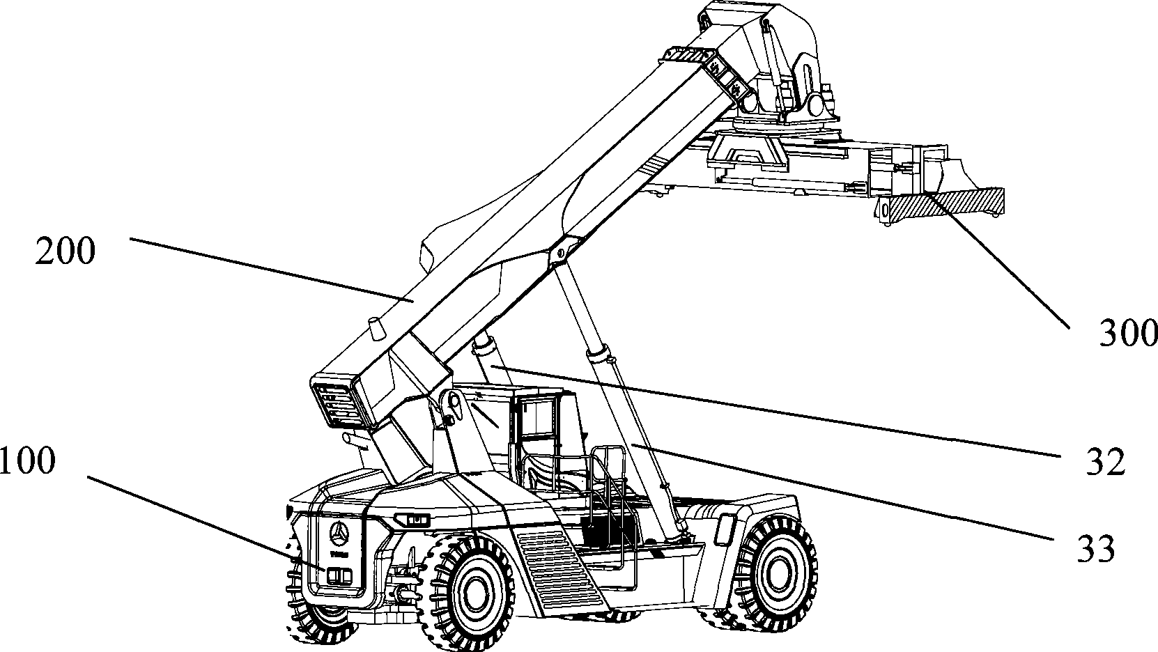
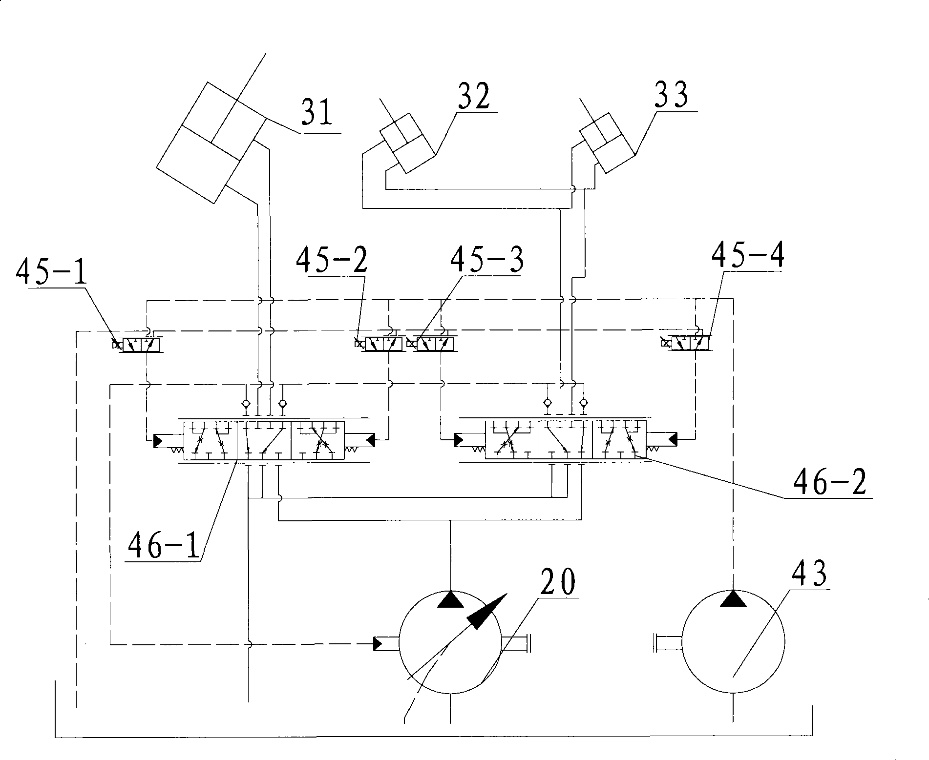
[0036] Embodiment 1 provides a container reach stacker, combined with figure 2 and image 3 , the container reach stacker includes an engine 10, a variable hydraulic pump 20, a telescopic oil cylinder 31, a left pitching oil cylinder 32, a right pitching oil cylinder 33 and a control system.

[0037] In this example, the variable hydraulic pump is preferably a swash plate variable displacement plunger pump with a pressure compensation variable mechanism. The swash plate variable displacement piston pump is convenient for displacement adjustment; Return to original displacement. Those skilled in the art can understand that the variable variable hydraulic pump can also be a variable variable inclined-axis plunger pump, or a variable variable vane pump.

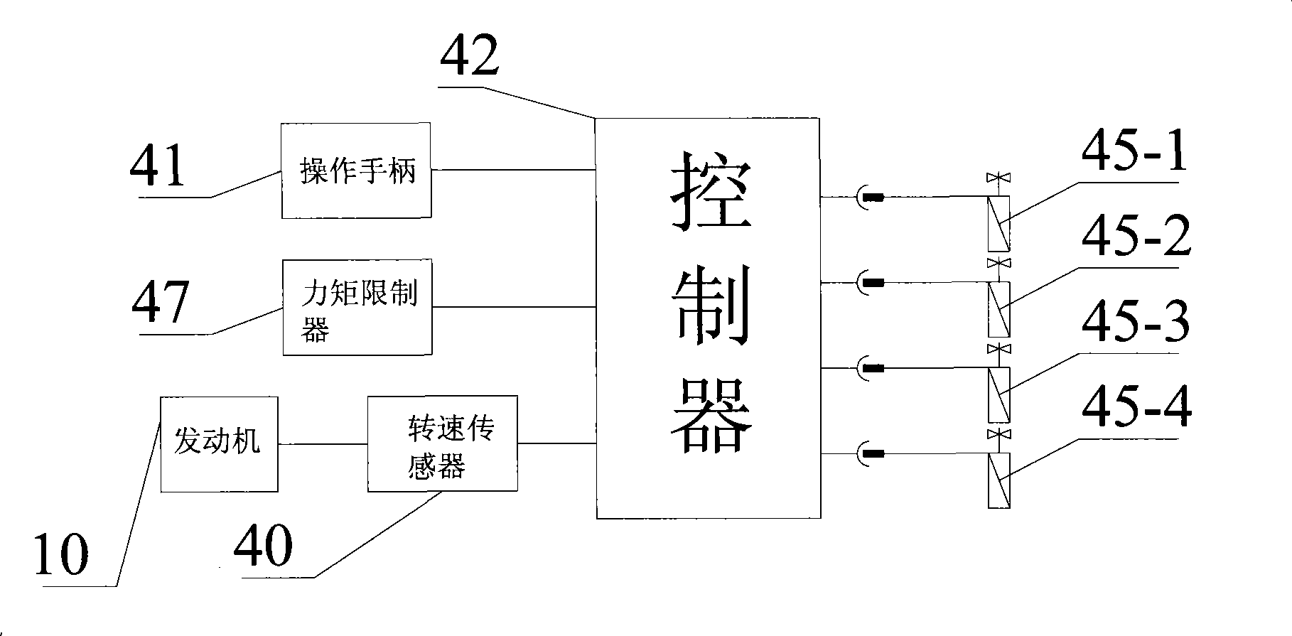
[0038] The control system includes a speed sensor 40, a torque limiter 47, an operating handle 41, a controller 42, an auxiliary hydraulic pump 43, four proportional pressure valves 45-1 to 45-4 and two proportional reversing...


PUM


Abstract

The invention discloses an engineering machine and a method for controlling the engineering machine. The engineering machine comprises an engine, a hydraulic pump, a hydraulic actuating mechanism and a control system, wherein the engine can drive the hydraulic pump which can supply high-pressure oil for the hydraulic actuating mechanism, the hydraulic actuating mechanism is used for driving corresponding components, the control system comprises an operating handle and a controller, and the hydraulic pump is a variable hydraulic pump; the controller can acquire the output power of the engine, external load and the adjustment range of the operating handle, and generate control signals according to a predetermined control policy; and the controller can adjust discharge capacity of the variable hydraulic pump through the control signals. The method for controlling the engineering machine comprises the following steps: firstly, acquiring the adjustment range of the operating handle, the external load and the output power of the engine; and secondly, adjusting the discharge capacity of the variable hydraulic pump according to actual working conditions. The engineering machine and the method for controlling the engineering machine can make load torque formed by the hydraulic pump matched with output torque of the engine.

Description

technical field [0001] The invention relates to a construction machine, and also relates to a control method of the construction machine. Background technique [0002] At present, many construction machinery are equipped with a power system powered by an engine and a hydraulic system powered by a hydraulic pump. The hydraulic system supplies high pressure oil. [0003] The output torque of the engine needs to match the load formed by the hydraulic pump and maintain a basic synchronous change; because the output torque of the engine is too small, it is easy to cause overload, the output speed is reduced, and the combustion performance of the engine fuel is affected, causing the engine to smoke. If the torque is too large and the overload is serious, it will even cause the engine output speed to drop sharply, causing the engine to stall; Increased fuel consumption. In order to avoid these technical problems, at present, construction machinery control systems generally inclu...

Claims


Application Information

Patent Timeline
Patent Type & Authority Applications(China)
IPC IPC(8): F15B9/04F15B21/02B66C23/693B66C23/82B66C13/18
Inventor 金晶廖荣华
Owner SANY MARINE HEAVY IND
Why Eureka
Try Eureka