
A drawer guide buffer mechanism

A buffer mechanism and drawer technology, applied in the field of medical devices, can solve problems such as increased friction, increased friction of connecting mechanisms, and easy sticking of lubricants to prevent strength failure, reduce friction, and low cost Effect

Active Publication Date: 2017-09-01
湖南迈瑞医疗科技有限公司
View PDF6 Cites 0 Cited by
  • Summary
  • Abstract
  • Description
  • Claims
  • Application Information

AI Technical Summary

Problems solved by technology

However, since the parts in the above-mentioned connection mechanism are rigidly connected between surfaces, there are the following disadvantages during its operation: 1) The parts of the connection mechanism adopt a surface-to-surface contact method, which increases the 2) Lubricants need to be rubbed between the parts of the connecting mechanism, which increases the maintenance of the instrument, and the lubricant is easy to stick to dust. After sticking to the dust, the friction of the connecting mechanism will also increase, which is more likely to cause damage to the connecting mechanism. 3) Each time the drawer is pushed and pulled, since the weight of each incubation detection seat is heavy, and the connection between the connection mechanism and the incubation detection seat is rigidly connected, the impact on the connection mechanism is very large, which shortens the life of the connection mechanism. There is even a loud noise when the drawer is pushed and pulled

Method used


Image

  • A drawer guide buffer mechanism
  • A drawer guide buffer mechanism
  • A drawer guide buffer mechanism

Examples


Embodiment Construction

[0039] In order to make the object, technical solution and advantages of the present invention clearer, the present invention will be further described in detail below in conjunction with the accompanying drawings.

[0040] The terms of direction and position mentioned in the present invention, such as "up", "down", "front", "back", "left", "right", "inside", "outside", "top", "bottom" ", "side", etc., are only referring to the direction or position of the drawings. Therefore, the terms used in direction and position are used to explain and understand the present invention, but not to limit the protection scope of the present invention.

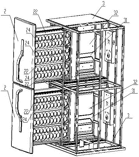
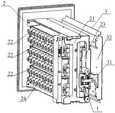
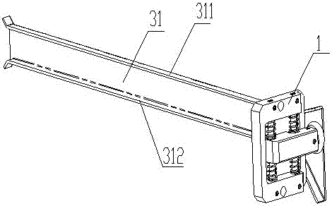
[0041] Such as Figure 1 to Figure 8 As shown, the embodiment of the present invention provides a drawer guiding and buffering mechanism, which is arranged in each box body 3 of the fully automatic microbial incubator. . The drawer guide buffer mechanism of the embodiment of the present invention includes a buffer mechanism 1 fixed on the ...


PUM


Abstract

The present invention provides a drawer guiding buffer mechanism, which includes a buffer mechanism and a chute; wherein, the buffer mechanism includes a buffer frame, a buffer rod, at least one sliding component, at least one elastic component, and a roller; the buffer frame includes a concave cavity and a frame; The buffer rod is located in the cavity, and there are at least two buffer rod through holes, one end of which has a bump, and rollers are installed on the end surface of the bump; the sliding parts are located in the cavity and pass through a buffer rod through hole respectively, and are fixed on the frame; The elastic part is sleeved on the outer surface of the sliding part outside the through hole of the buffer rod, and abuts against the outer surface of the buffer rod and the inner wall of the concave cavity; the inner surface of the roller chute matches and can slide in the chute. The drawer guide buffer mechanism provided by the embodiment of the present invention has a simple structure and low cost, can not only position and guide, but also prevent strength failure and reduce noise generated during operation.

Description

technical field [0001] The invention relates to the technical field of medical devices, in particular to a drawer guiding buffer mechanism. Background technique [0002] The automatic microbial culture instrument is a microbiological inspection instrument used to test the presence or absence of bacteria in body fluids (mainly blood). The sample bottles placed in the automatic microbial culture instrument need to be continuously incubated at constant temperature and shaken , in order to ensure better growth and amplification of microorganisms, and increase the accuracy of determining whether there are bacteria. [0003] The automatic microbial culture instrument is a fully automatic drawer type, with one or more boxes, each box contains a drawer, and each drawer is equipped with one or more incubation test seats, and each incubation test seat contains multiple layers Vial wells, each of which can hold one vial. On the one hand, in order to facilitate the taking and placing ...

Claims


Application Information

Patent Timeline
Patent Type & Authority Patents(China)
IPC IPC(8): C12M1/00
Inventor 王荣罗继全张茂林
Owner 湖南迈瑞医疗科技有限公司
Learn More