
Reciprocating drive mechanism and its cable arrangement and take-up machine

A technology of driving mechanism and wire arranging device, which is applied in the direction of thin material processing, conveying filamentous materials, transportation and packaging, etc. It can solve the problems of inability to meet individual requirements, complicated adjustment process, inconvenient adjustment of screw rod wire arranging device, Problems such as return speed, to achieve the effect of simple and reliable debugging, large free adjustment range, and improved accuracy

Active Publication Date: 2021-07-23
LUSHAN COLLEGE OF GUANGXI UNIV OF SCI & TECH +1
View PDF1 Cites 0 Cited by
  • Summary
  • Abstract
  • Description
  • Claims
  • Application Information

AI Technical Summary

Problems solved by technology

The screw cable arranging device avoids the problem of slipping when arranging the cable through the self-locking effect of the screw rod and the nut, but because the movement speed of the screw rod cable arranging device needs to be controlled by the drive motor that drives the driving sprocket on the take-up reel shaft to rotate. Adjustment, and the change of the speed of the driving motor will cause the speed of the take-up reel to change together. Therefore, the adjustment process is complicated. Therefore, the reciprocating speed of the threaded screw is usually set to be the same, and it is also inconvenient to adjust the screw separately. The reciprocating and reciprocating speed of the cable arrangement cannot meet the individual requirements of some manufacturers for the different requirements for the reciprocating and reciprocating speed of the cable arrangement.

Method used

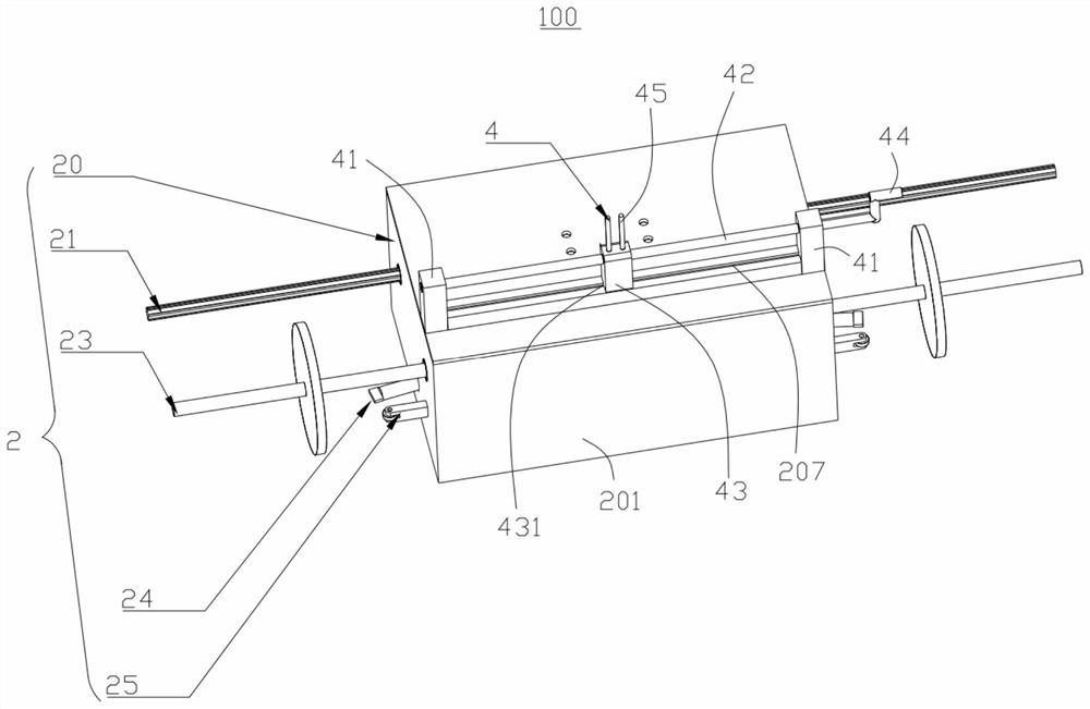
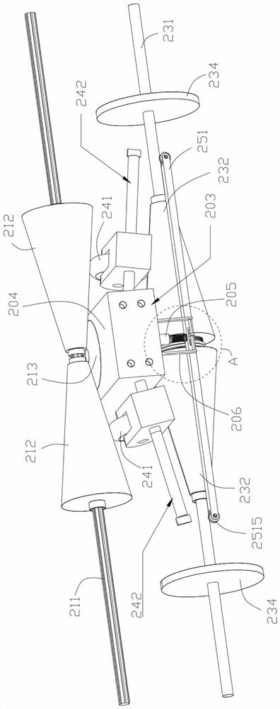
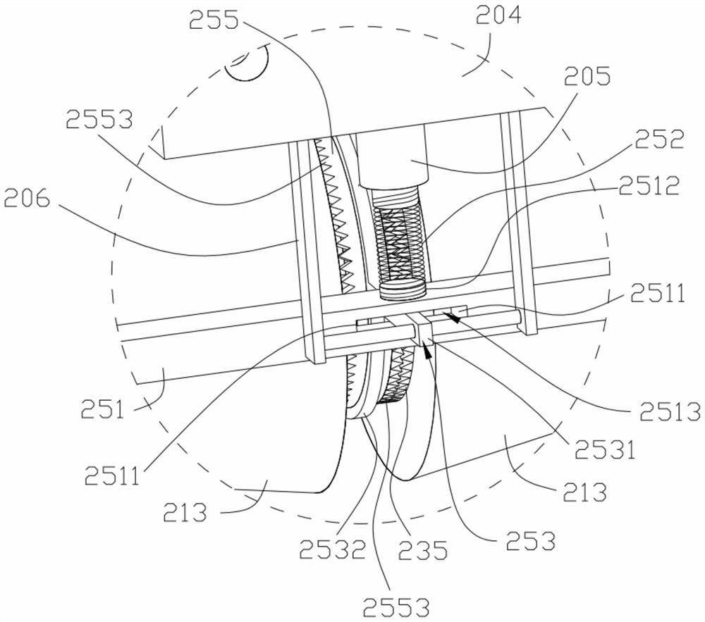

Image

  • Reciprocating drive mechanism and its cable arrangement and take-up machine
  • Reciprocating drive mechanism and its cable arrangement and take-up machine
  • Reciprocating drive mechanism and its cable arrangement and take-up machine

Examples


Embodiment Construction

[0040] The following will clearly and completely describe the technical solutions in the embodiments of the present invention with reference to the accompanying drawings in the embodiments of the present invention. Obviously, the described embodiments are only some, not all, embodiments of the present invention. Based on the embodiments of the present invention, all other embodiments obtained by persons of ordinary skill in the art without making creative efforts belong to the protection scope of the present invention.

[0041] It should be noted that when a component is said to be "fixed" to another component, it can be directly on the other component or there can also be an intervening component. When a component is said to be "connected" to another component, it may be directly connected to the other component or there may be intervening components at the same time. When a component is said to be "set on" another component, it may be set directly on the other component or t...


PUM


Abstract

A wire straightener, including a cycloid and a reciprocating drive mechanism, the reciprocating drive mechanism includes a slide table connected to the cycloid, a power input assembly, a power output assembly, two speed regulating parts and a reversing assembly; the power input assembly includes The driving shaft passing through the sliding table, the two driving cone wheels and the driving cone wheel connected with the sliding table, the driving cone wheel is sleeved on the driving shaft and in contact with the driving cone wheel; the power output assembly includes the screw rod passing through the sliding table and Two driven cone wheels that are vacantly sleeved on the screw rod and connected with the slide table. The driven cone wheel is provided with output teeth; The flywheel drive connected to the speedwheel; the reversing assembly includes a reversing nut screwed with the screw rod, a reversing gear sleeved on the reversing nut, and a reversing gear used to drive the reversing gear to alternately connect with two output teeth. The engaged reversing gear position regulator can separately adjust the reciprocating speed of the cable, and the present invention also provides a wire take-up machine with it and a reciprocating drive mechanism used therein.

Description

technical field [0001] The invention relates to a drive device, in particular to a reciprocating drive mechanism and a cable puller and a take-up machine with the same. Background technique [0002] The wire take-up machine is a kind of equipment that collects the wires. It usually includes a frame and a wire arranger installed on the frame, a wire take-up reel, a power device and other mechanisms, and the power device and the wire reel take-up reel The connection is used to drive the take-up reel to rotate, and the power device is connected to the cable guide through the transmission mechanism, which is used to drive the cable guide to reciprocate along the axial direction of the take-up reel, so that the cables, etc. are wound on the take-up reel Take-up on the drum. [0003] The current cable arrangement usually includes a polished rod cable arrangement and a screw cable arrangement. Among them, the polished rod cable arrangement is mainly composed of a polished rod, a ...

Claims


Application Information

Patent Timeline
Patent Type & Authority Patents(China)
IPC IPC(8): B65H54/30B65H54/00
CPCB65H54/00B65H54/30
Inventor 林澎樊玉广骆蜜陈嘉欣潘宇倩丁伟林浩明胡伟陈丽洁韦微陆忠群卢建忠
Owner LUSHAN COLLEGE OF GUANGXI UNIV OF SCI & TECH
Learn More