Jacking device used for mounting of steel structure net rack and using method of jacking device

A lifting device and steel structure technology, which is applied in the direction of lifting device, lifting equipment safety device, packaging, etc., can solve the problems of time-consuming and laborious, and the lifting device does not have an automatic feeding mechanism, so as to reduce the number of workers and increase the consumption of food. Safety, the effect of speeding up the cutting speed

Active Publication Date: 2021-03-12
安徽盛世开元装备科技有限公司
View PDF12 Cites 0 Cited by
  • Summary
  • Abstract
  • Description
  • Claims
  • Application Information

AI Technical Summary

Problems solved by technology

[0003] Existing jacking devices for the installation of steel structure grids usually do not have an automatic unloading mechanism, and the bottom of the silo is directly fixed and welded to the top surface of the mounting seat, and the top of th

Method used


Image

  • Jacking device used for mounting of steel structure net rack and using method of jacking device
  • Jacking device used for mounting of steel structure net rack and using method of jacking device
  • Jacking device used for mounting of steel structure net rack and using method of jacking device

Examples


Embodiment 1

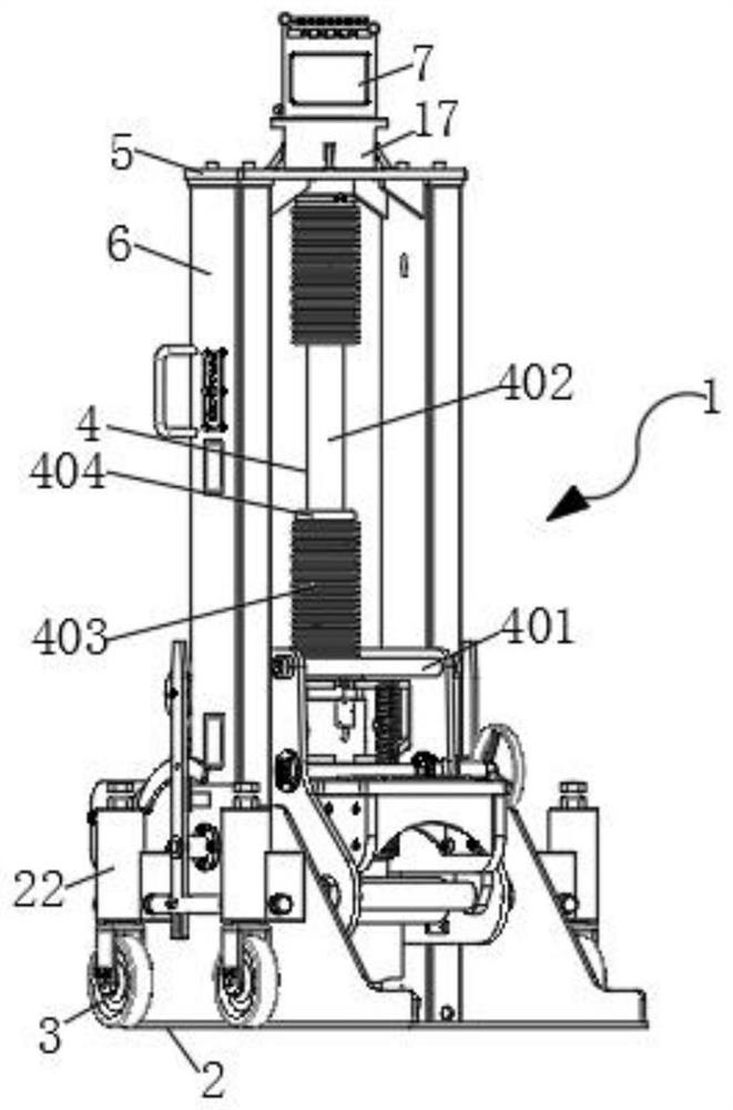
[0043] like Figure 1-2 As shown, a jacking device for steel structure grid installation includes a jacking mechanism 1, and the jacking mechanism 1 includes a base 2, rolling wheels 3, jacking parts 4, a top plate 5 and two side plates 6 , the two side plates 6 are fixedly installed on both sides of the top surface of the base 2 respectively, the lifting part 4 is arranged between the two side plates 6, and the top plate 5 is fixedly installed on the top of the two side plates 6 Between, the top surface of the top plate 5 is provided with a silo 7;

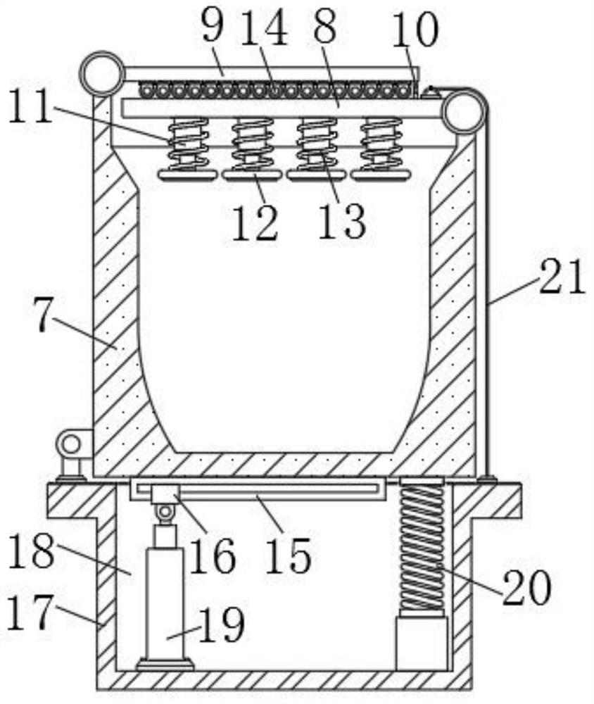
[0044] The inner wall of the silo 7 is arranged in an arc shape, and the two sides of the silo 7 are respectively hinged with a pressing plate 8 and a blanking plate 9, and the pressing block 12 at the bottom of the pressing plate 8 is under the action of the first spring 13 The grid parts in the feed bin 7 can be compressed, and the blanking roller 14 on the bottom surface of the blanking plate 9 is convenient for the grid part...

Embodiment 2

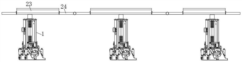
[0066] like image 3 As shown, the difference between this embodiment and Embodiment 1 is that there are multiple jacking mechanisms 1, the bottoms of multiple jacking mechanisms 1 are located on the same horizontal line, and the output ends of the jacking cylinders 402 of multiple jacking mechanisms 1 are all A discharge chute 23 is fixedly installed, and connection plates 24 are fixedly installed on both sides of the discharge chute 23, and the adjacent ends of two adjacent connection plates 24 are hinged, and a plurality of discharge chutes 23 are formed with the connection plate 24 A material trough used to prevent the whole grid frame. Workers can install the steel structure grid frame on the flat ground, and after the installation is completed, place the grid frame as a whole inside the material tank, and simultaneously jack up the grid frame by multiple jacking devices The grid frame is transported upwards; this jacking method can lift and transport the grid frame as a ...


PUM


Abstract

The invention belongs to the field of net rack mounting, and relates to the technology of jacking equipment, in particular to a jacking device used for mounting of a steel structure net rack and a using method of the jacking device. The jacking device comprises a jacking mechanism, the jacking mechanism comprises a base, rolling wheels, a jacking component, a top plate and two side plates, the twoside plates are fixedly mounted on the two sides of the top face of the base correspondingly, the jacking component is arranged between the two side plates, the top plate is fixedly mounted between the tops of the two side plates, and a material bin is arranged on the top face of the top plate. The material bin is hinged to a mounting seat, and a first electric push rod is arranged in a groove ofthe mounting seat, the material bin can automatically rotate and incline for discharging after being jacked to a mounting platform, and therefore manual discharging is not needed after the material bin is jacked to the mounting platform, the working pressure of workers is reduced, and the discharging speed can be increased.

Description

technical field [0001] The invention belongs to the field of net frame installation, relates to jacking equipment technology, in particular to a jacking device for steel structure net frame installation and a use method thereof. Background technique [0002] Due to its beautiful architectural shape and easy and fast on-site installation, steel structure grids are widely used in large public buildings, such as stadiums and airports. Due to the small and many assembled structural units, large-scale equipment cannot be used. Therefore, on-site construction, It is usually necessary to set up and install a construction work platform during installation. [0003] Existing jacking devices for the installation of steel structure grids usually do not have an automatic unloading mechanism, and the bottom of the silo is directly fixed and welded to the top surface of the mounting seat, and the top of the silo equipped with grid parts is placed on the top of the lifting device. After r...

Claims


Application Information

Patent Timeline
IPC IPC(8): B66F3/25B66F3/46B66F17/00E04G21/16F16F15/067G06Q10/00G06Q10/06G06Q50/08B65G65/23B65G65/38
CPCB66F3/247B66F3/25B66F3/46B66F17/00F16F15/067E04G21/162B65G65/23B65G65/38G06Q50/08G06Q10/06G06Q10/20
Inventor 宫开元宫硕辰崔丙贤苏雨奇
Owner 安徽盛世开元装备科技有限公司
Why Eureka
Try Eureka