
Electric parking brake actuator assembly

An actuator and electronic technology, which is applied in the direction of electric components, brake actuators, brakes, etc., can solve the problems of increased manufacturing time and manufacturing costs, reduced gear durability, and reduced product durability, so as to reduce the defective rate, The effect of reducing the number and reducing glitches

Active Publication Date: 2021-03-12
KEYANG ELECTRIC MACHINERY
View PDF12 Cites 0 Cited by
  • Summary
  • Abstract
  • Description
  • Claims
  • Application Information

AI Technical Summary

Problems solved by technology

When the center distance between the rotating axes deviates from the allowable range due to accumulated tolerances between parts, there may be quality problems such as performance degradation or noise generation
In particular, motor vibration generated during operation due to such accumulated tolerances causes rattling of parts such as gears, and reduces the durability of the gears, thereby reducing the durability of the product
[0004] This is because, when assembling various components such as the built-in motor and gears, it is difficult to precisely align the shafts between the various components, especially, the gear assembly (or gearbox) for performing the deceleration function is an additional structure different from the motor assembly , which increases the internal structure, makes tolerance management difficult due to tolerance build-up, and therefore makes it more difficult to align axes between parts that are spaced apart from each other
[0005] In addition, since the actuator has a large number of built-in parts, the number of processes required to assemble each part increases, resulting in an increase in manufacturing time and manufacturing costs.

Method used


Image

  • Electric parking brake actuator assembly
  • Electric parking brake actuator assembly
  • Electric parking brake actuator assembly

Examples


Embodiment Construction

[0065] Hereinafter, some embodiments of the present invention will be described in detail through schematic diagrams. It should be noted that when assigning reference signs to structures in each drawing, the same reference signs should be used as much as possible even if the same structural elements are marked in different drawings. Moreover, when describing the embodiments of the present invention, if it is considered that the specific description of related known structures or functions is not conducive to the understanding of the embodiments of the present invention, the detailed description will be omitted.

[0066] Also, terms such as first, second, A, B, (a), and (b) can be used when describing the constituent elements of the embodiments of the present invention. Such terms are only for distinguishing the structural elements from other structural elements, and the nature, order or sequence, etc. of the corresponding structural elements are not limited by the terms. When...


PUM


Abstract

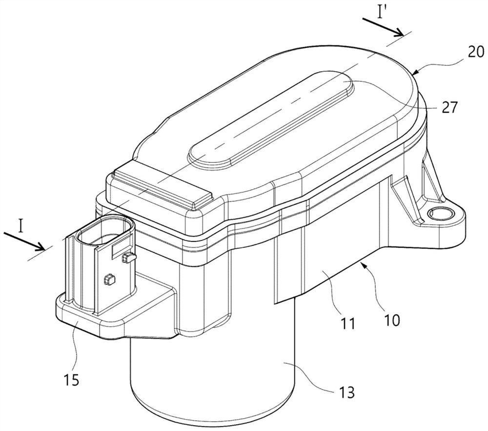
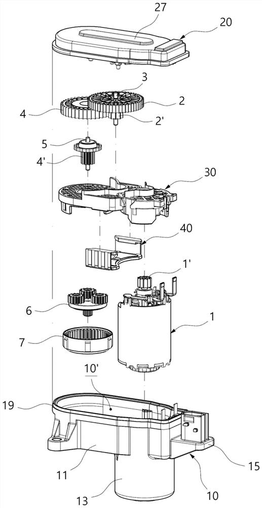
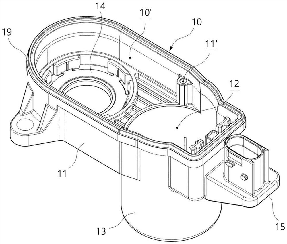
An electric parking brake actuator assembly is proposed. The electric parking brake actuator assembly includes: an outer housing (10) including an inner space (10') in which a gear installation space(14) and a motor installation space (12) are formed; an inner housing (30) installed in the inner space (10') of the outer housing (10), and including a brush card part (31) and a gear installation part (34) integrated together; a motor assembly (1) coupled to the brush card part (31) to be electrically connected thereto, and installed in the motor installation space (12); a gear assembly installed at the gear installation part (34) and at the gear installation space (14), and changing and transmitting the rotational speed of the motor assembly (1); and a cover housing (20) coupled to the outer housing (10) with the inner housing (30) interposed therebetween, and including a shaft insertion portion.

Description

technical field [0001] The present invention relates to an electronic parking brake actuator assembly, in more detail, relates to an electronic parking brake actuator assembly with simplified internal structure. Background technique [0002] The electric parking brake actuator of the automobile operates the friction pads of the calipers (Caliper) provided on the disc brake (disc brake) device when the vehicle is parked. The electronic parking brake is automatically operated by a user's switch operation, and for this purpose, is composed of an electronic parking brake motor and a gear assembly (power transmission device) for transmitting power of the motor. In the case of using the electronic parking brake as described above, when the driver presses the parking brake switch, the rotational force of the motor of the actuator is transmitted to the caliper through a gear assembly (power transmission device) such as a reduction gear. Input shaft. When the input shaft receiving ...

Claims


Application Information

Patent Timeline
Patent Type & Authority Applications(China)
IPC IPC(8): F16D65/14F16H57/023F16H57/02F16H57/03H02K7/116F16D121/24
CPCF16D65/14F16H57/023F16H57/02F16H57/03H02K7/116F16D2121/24F16D2125/50B60T13/741F16D65/18F16D2131/02B60T13/746F16H1/32B60Y2400/73F16D65/16F16H1/28F16H57/021F16H57/031F16H2057/02034F16H2057/02082B60T7/045
Inventor 张洙吉李虎建朴长寿李相训
Owner KEYANG ELECTRIC MACHINERY
Learn More