
Special-shaped nozzles for main-stage oil supply of lean-fuel premixed pre-evaporated low-pollution combustors

A combustion chamber and pre-evaporation technology, applied in the direction of combustion chambers, continuous combustion chambers, combustion methods, etc., can solve the problems of increased NOx generation of pollutants, insufficient penetration depth of circular hole jets, poor atomization effect of direct nozzles, etc. Achieve the effects of increased penetration depth, increased spatial distribution uniformity, and increased oil and gas mixing efficiency

Active Publication Date: 2022-01-04
NANJING UNIV OF AERONAUTICS & ASTRONAUTICS
View PDF5 Cites 0 Cited by
  • Summary
  • Abstract
  • Description
  • Claims
  • Application Information

AI Technical Summary

Problems solved by technology

In the lean fuel premixed pre-evaporative combustion chamber, fuel and air are combusted in stages and zones to achieve the goal of low pollution emissions. The main stage fuel is directly injected with direct injection nozzles, and the traditional direct injection nozzles are all regular circles. Insufficient jet penetration depth of holes and circular holes, poor atomization effect of direct injection nozzles, and uneven distribution of fuel space in the circumferential direction of the main stage swirler, insufficient mixing of oil and gas, fuel enrichment will occur downstream of each circular hole injection point area, leading to the formation of a local high-temperature area at the outlet of the main stage, resulting in an increase in the generation of pollutants NOx

Method used


Image

  • Special-shaped nozzles for main-stage oil supply of lean-fuel premixed pre-evaporated low-pollution combustors
  • Special-shaped nozzles for main-stage oil supply of lean-fuel premixed pre-evaporated low-pollution combustors
  • Special-shaped nozzles for main-stage oil supply of lean-fuel premixed pre-evaporated low-pollution combustors

Examples


Embodiment Construction

[0032] In order to make the purpose and effect of the present invention clearer, the present invention will be further described in detail below with reference to the accompanying drawings. It should be pointed out that the specific working process described here is only used to explain the present invention, not to limit the present invention.

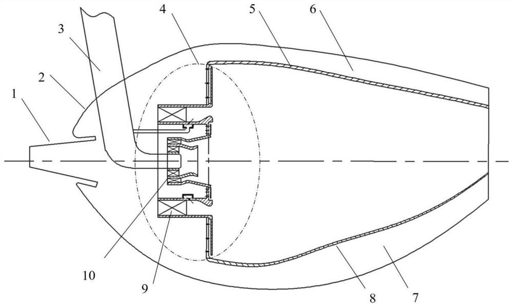
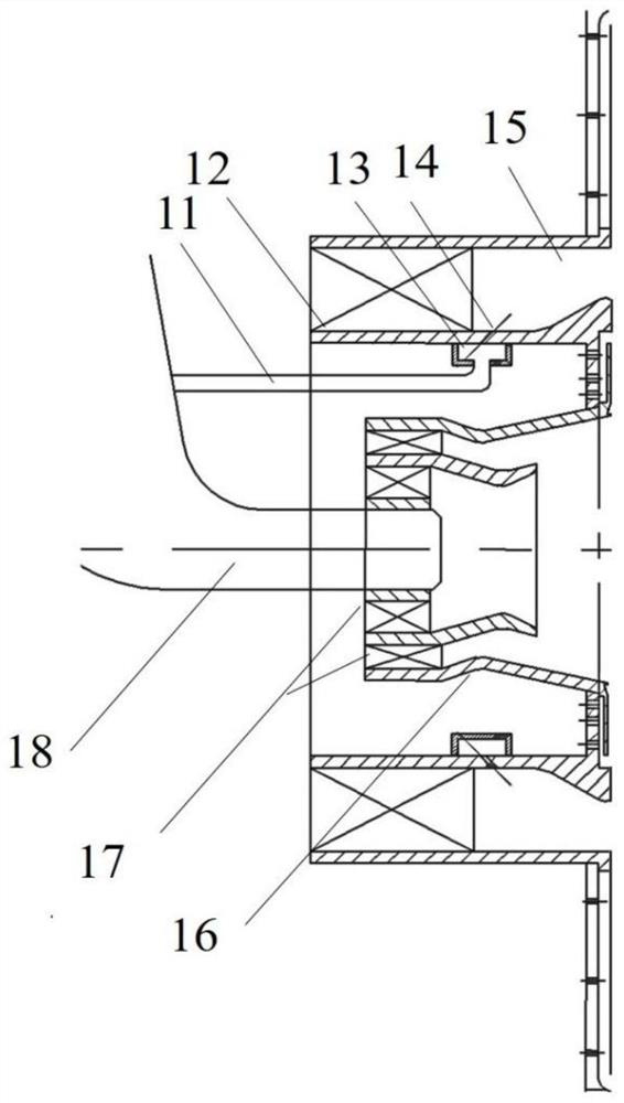
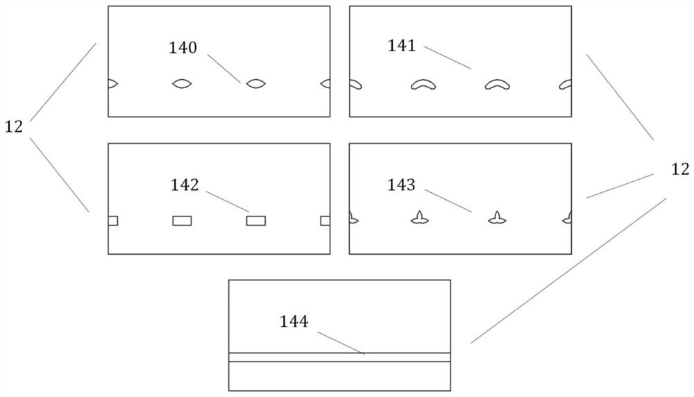
[0033] like figure 1 As shown, it is a structural schematic diagram of the fuel-lean premixed pre-evaporation low-pollution combustion chamber with a special-shaped nozzle of the present invention, including a diffuser 1 and a combustion chamber casing 2 arranged at its rear end, an oil injection rod 3, and an inner ring passage in the combustion chamber 7. The combustion outer ring passage 6; it is characterized in that the fuel injection rod 3 is installed on the combustion chamber casing 2, and the fuel injection rod 3 is respectively provided with dual oil nozzles 18 on duty and main oil supply pipes 11. Road pipe; the interior o...


PUM


Abstract

The invention relates to a special-shaped nozzle for the main-stage oil supply of a lean-oil premixed pre-evaporation low-pollution combustion chamber, which belongs to the field of gas turbine combustion; the invention sets a special-shaped nozzle hole in the air flow channel of the main-stage swirler to form a main-stage oil supply nozzle. Oil direct injection special-shaped nozzles; the special-shaped nozzles are evenly distributed along the circumferential direction of the main swirler to form a uniformly distributed fuel space distribution in the circumferential direction, increase the contact area between fuel and air, improve the mixing effect of oil and gas, and improve the uniform distribution of fuel It can reduce the local high temperature zone caused by fuel enrichment after the main injection hole, thereby effectively reducing the generation of NOx, CO and other pollutants. By changing the fuel jet penetration depth, jet direction and jet circumferential expansion angle of the main-stage direct injection nozzle hole, the effect of adjusting the temperature uniform distribution downstream of the main-stage nozzle hole is achieved, and the generation of NOx, CO and other pollutants is reduced.

Description

technical field [0001] The invention belongs to the field of combustion of gas turbines, and in particular relates to a special-shaped nozzle used for the main-stage oil supply of lean oil premixed pre-evaporation low-pollution combustion chambers. Background technique [0002] At present, civil aviation engines emit more and more pollutants into the atmosphere, and the air pollution is also becoming more and more serious. In order to control the impact of aircraft engine emissions on the environment, the pollution emissions from civil aircraft combustion chambers are required to meet the ICAO CAEP standards, and NO X Emissions requirements are getting stricter. At present, lean oil premixed pre-evaporation low-pollution combustion technology is often used in civil aeroengine combustors to reduce NO X emission. In the lean fuel premixed pre-evaporative combustion chamber, fuel and air are combusted in stages and zones to achieve the goal of low pollution emissions. The ma...

Claims


Application Information

Patent Timeline
Patent Type & Authority Patents(China)
IPC IPC(8): F23R3/28F23R3/38
CPCF23R3/38F23R3/286
Inventor 张萍颜应文李伟刘云鹏李井华田泽民
Owner NANJING UNIV OF AERONAUTICS & ASTRONAUTICS
Learn More