Loudspeaker

A loudspeaker and skeleton technology, applied in the field of loudspeakers, can solve the problems of large vibration amplitude of the diaphragm, affecting the motion stability of the vibration system, affecting the sound quality of the loudspeaker, etc., to achieve the effect of solving the swing

Active Publication Date: 2021-03-12
RUISHENG NEW ENERGY DEV CHANGZHOU +1
View PDF11 Cites 0 Cited by
  • Summary
  • Abstract
  • Description
  • Claims
  • Application Information

AI Technical Summary

Problems solved by technology

[0003] Existing loudspeakers generally include a pot frame and a diaphragm housed in the pot frame, a voice coil and a magnetic element. The voice coil drives the diaphragm to vibrate under the drive of the magnetic element. For some speakers, the vibration amplitude of the

Method used


Image

  • Loudspeaker
  • Loudspeaker
  • Loudspeaker

Examples


Embodiment 1

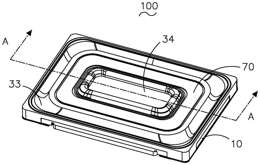
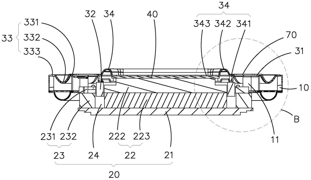
[0032] combine Figure 1 to Figure 6 As shown, the loudspeaker 100 of the present invention is schematically shown, including the basin frame 10 having the accommodation space 11 and the magnetic circuit system 20 and the vibration system 30 accommodated in the accommodation space 11 .

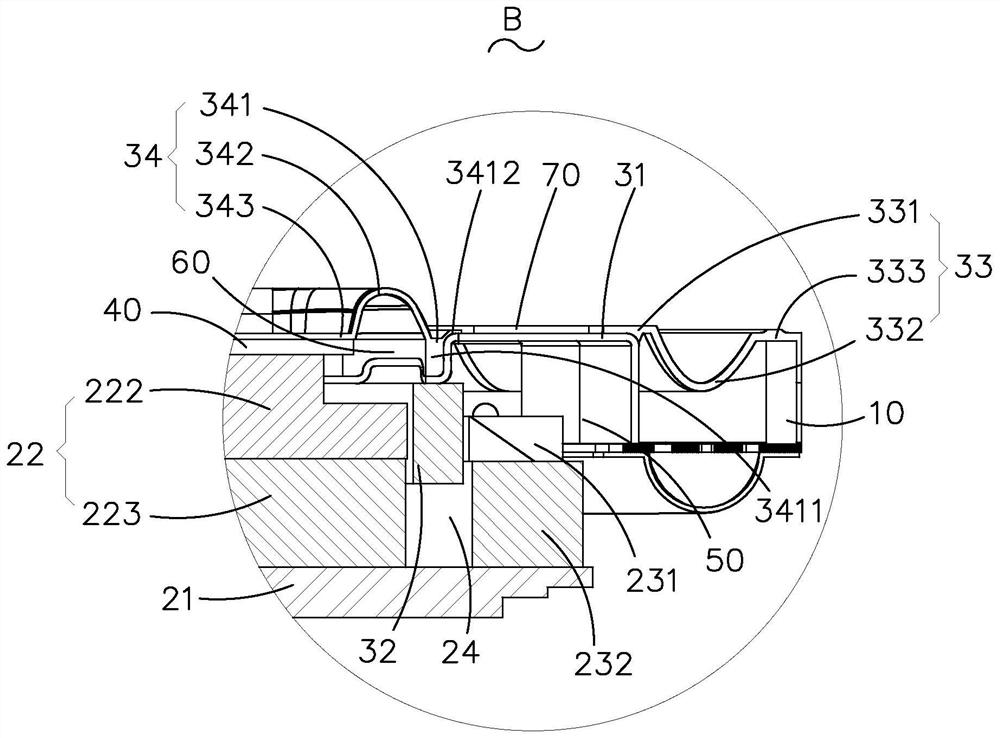
[0033] The magnetic circuit system 20 includes a yoke 21, a main magnetic circuit assembly 22, and an auxiliary magnetic circuit assembly 23 that is spaced apart from the main magnetic circuit assembly 22 to form a magnetic gap 24. Both the main magnetic circuit assembly 22 and the auxiliary magnetic circuit assembly 23 are fixed on the yoke. 21 , the yoke 21 is fixedly connected to the frame 10 .

[0034] The vibration system 30 includes a skeleton 31, a voice coil 32 and a diaphragm. The diaphragm is fixed to the frame 10. Specifically, the diaphragm includes a middle membrane 34 located in the middle and an outer sound membrane 33 surrounding the middle membrane 34 at intervals. The voice c...

Embodiment 2

[0043] The difference between this embodiment and Embodiment 1 is that the main magnetic circuit assembly 22 includes a main magnetic steel 223, and the second fixing part 343 is fixed on the end of the main magnetic steel 223 close to the middle membrane 34, that is, compared with the first embodiment, the The main pole core 222 . This structure also enables the skeleton 31 to be connected to the main magnetic circuit assembly 22 through the middle membrane 34, and the middle membrane 34 can limit the swing of the skeleton 31 and the voice coil 32, which effectively solves the swinging problem of the vibration system 30 of the current loudspeaker 100 .


PUM


Abstract

The invention provides a loudspeaker, which comprises a basin frame, a vibration system fixed on the basin frame and a magnetic circuit system with a magnetic gap, and is characterized in that the magnetic circuit system comprises a magnet yoke and a main magnetic circuit assembly fixed on the magnet yoke, the vibration system comprises a vibrating diaphragm fixed on the frame, a skeleton fixed onone side of the vibrating diaphragm facing the magnetic circuit system, and a voice coil inserted into the magnetic gap through the skeleton, the skeleton is annular, the vibrating diaphragm comprises a middle diaphragm located in the middle and outer voice diaphragms surrounding the middle diaphragm at intervals, the edges of the outer voice diaphragms away from the middle diaphragm are fixed onthe frame, the skeleton is connected with the outer voice diaphragms and the middle diaphragm, and the middle diaphragm comprises a first side connected to the skeleton and a second side connected toa main pole core; a boss is arranged at one end, close to the middle diaphragm, of the main pole core, the boss is provided with a second connecting surface arranged towards the second side of the middle diaphragm, and the second side of the middle diaphragm is fixed on the second connecting surface; as the skeleton is connected to the main pole core through the middle diaphragm, the middle diaphragm can limit the swinging of the skeleton and the voice coil, and the problem that an existing loudspeaker vibration system swings is effectively solved.

Description

【Technical field】 [0001] The invention relates to the technical field of electronic components, in particular to a loudspeaker. 【Background technique】 [0002] The loudspeaker is a transducer device that converts electrical signals into acoustic signals. It is widely used in convenient electronic devices such as mobile phones, laptop computers, and portable music players. With the rapid development of these convenient electronic devices, people's functions The performance requirements are getting higher and higher, especially for the speakers used in mobile phones, and the speakers used in these electronic devices also need corresponding development. [0003] Existing loudspeakers generally include a pot frame and a diaphragm housed in the pot frame, a voice coil and a magnetic element. The voice coil drives the diaphragm to vibrate under the drive of the magnetic element. For some speakers, the vibration amplitude of the diaphragm itself Large, the diaphragm and voice coil...

Claims


Application Information

Patent Timeline
IPC IPC(8): H04R7/12H04R9/02H04R9/04H04R9/06
CPCH04R7/122H04R9/025H04R9/04H04R9/06
Inventor 肖波章统孔晨亮令狐荣林
Owner RUISHENG NEW ENERGY DEV CHANGZHOU
Why Eureka
Try Eureka