Reinforcement Cage Welding or Lashing Devices

A steel cage and stirrup technology, applied in welding equipment, auxiliary devices, auxiliary welding equipment, etc., can solve the problems of easy bending and deformation of longitudinal bars, narrow use range, shaking or swaying, etc., so as to reduce the labor intensity of workers and improve production. Efficiency and high degree of automation

Active Publication Date: 2021-07-27
CHINA MINSHENG ZHUYOU
View PDF8 Cites 0 Cited by
  • Summary
  • Abstract
  • Description
  • Claims
  • Application Information

AI Technical Summary

Problems solved by technology

In the prior art, most of the longitudinal bars and stirrups are positioned by the same device, so the range of use of the device is relatively narrow, and it is difficult to produce steel cages of different shapes
By researching the current reinforcement cage welding or binding device, it is found that there are following disadvantages: first, when making a 2-story or 3-story high reinforcement cage, the longitudinal reinforcement used is as long as 6m or 9m, and the existing device exists There are few clamping points of the longitudinal reinforcement, and the longitudinal reinforcement is easy to bend and deform; secondly, due to some errors in the production process of the stirrup, the width or length of the stirrup is not exactly the same, so the stirrup is placed in the stirrup slot of the existing device Occasional shaking or wobbling problems
[0004] To sum up, there is an urgent need to develop a reinforcement cage welding or binding device to solve the existing problems in the prior art. During the production of the reinforcement cage, the longitudinal reinforcement is easy to bend and deform, and the stirrup tends to appear in the groove. Technical problems such as shaking and shaking

Method used


Image

  • Reinforcement Cage Welding or Lashing Devices
  • Reinforcement Cage Welding or Lashing Devices
  • Reinforcement Cage Welding or Lashing Devices

Examples


Embodiment 1

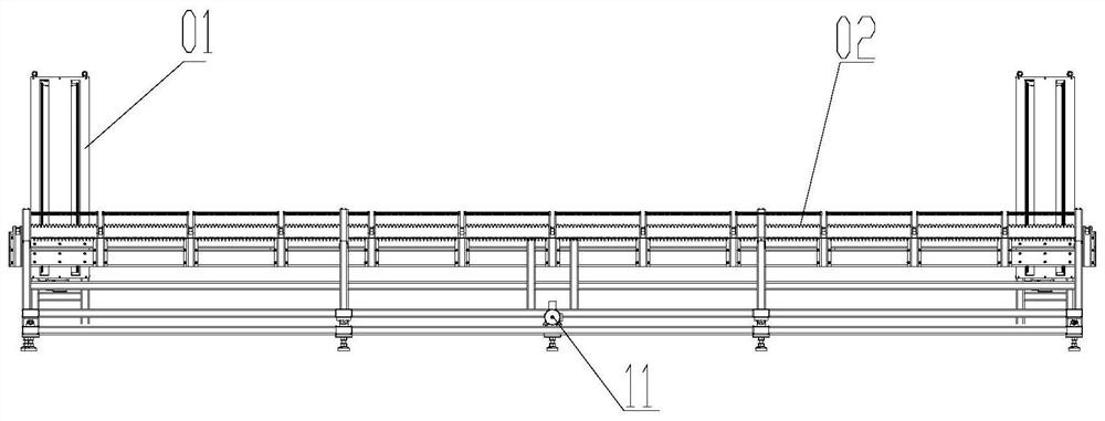
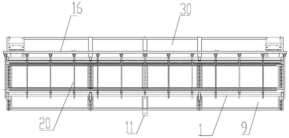
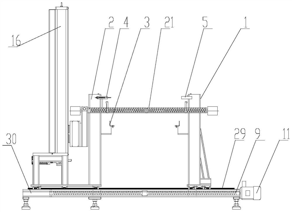
[0048] Reference attached figure 1 to attach Figure 4As shown, the steel cage welding or binding device in this embodiment includes a longitudinal bar positioning machine 01 and a stirrup bar positioning machine 02, and the longitudinal bar positioning machine 01 includes a lifting seat 16 and a plurality of longitudinal bar supports arranged on the lifting seat 16 Assemblies 20, each longitudinal reinforcement support assembly 20 includes support bars 21 horizontally arranged for supporting longitudinal reinforcement 15; Two stirrup retaining mechanisms 1, each set of stirrup retaining mechanisms 1 includes a vertically arranged fixed plate 2 and a retaining plate 3 arranged on the side of the fixed plate 2, and the retaining plate 3 is provided with a plurality of accommodating stirrups 12, the slot of the first stirrup clamping mechanism and the clamping slot of the second stirrup clamping mechanism 1 are opposite to form a stirrup receiving groove. The longitudinal bar ...


PUM


Abstract

The invention discloses a reinforcement cage welding or binding device, which includes a longitudinal bar positioning machine and a stirrup bar positioning machine. The longitudinal bar positioning machine includes a lifting seat and a plurality of longitudinal bar supporting components arranged on the lifting seat. The support assembly includes a support rod arranged horizontally for supporting the longitudinal reinforcement; the stirrup positioning machine includes a first stirrup clamping mechanism and a second stirrup clamping mechanism arranged in parallel, both of which include vertically disposed fixing plates and The clamping plate arranged on the side of the fixing plate, the clamping plate is provided with a plurality of clamping grooves for accommodating stirrups, the clamping grooves of the first stirrup clamping mechanism and the clamping grooves of the second stirrup clamping mechanism are opposite to form a stirrup Storage tank. The stirrup positioning machine and the longitudinal bar positioning machine of this scheme constitute a complete set of reinforcement cage welding equipment, which can realize the stability of the positioning of the stirrups and longitudinal bars, and ensure the stability of the stirrups and longitudinal bars in the production process of the steel cage. It is suitable for the production of steel cages of different shapes, reducing the labor intensity of workers and improving the production efficiency of steel cages.

Description

technical field [0001] The invention belongs to the technical field of construction engineering devices, in particular, the invention relates to a reinforcement cage welding or binding device. Background technique [0002] In the construction industry, a large number of steel cages need to be applied. At present, the production of steel cages mainly adopts manual binding or steel cage roll welding. The effect of manual binding and forming is affected by the working environment and operators; the most common product on the market is a cylindrical seam welding machine for steel cage seam welding, which has high welding efficiency and can only be used for a single type of steel cage in automatic production , so that the steel cage products that can be processed are subject to certain limitations. However, if complex structures or special-shaped steel cages are required, the existing equipment needs to be modified; or the manual binding method with low production efficiency is ...

Claims


Application Information

Patent Timeline
Patent Type & Authority Patents(China)
IPC IPC(8): B23K37/04B21F15/08
CPCB21F15/08B23K37/0443
Inventor 黄岸薛英杰林艳江
Owner CHINA MINSHENG ZHUYOU
Why Eureka
Try Eureka