Double-plate swirling rectification anti-drag stabilizer of speed boat

An anti-rolling device and technology for speedboats, which are applied to ships, transportation and packaging, and equipment for reducing ship motion, etc., can solve the problems of adverse effects of speedboats' state and speed, increased forward resistance of speedboats, and unsatisfactory anti-rolling effects, etc. , to achieve the effect of improving the hydrodynamic performance defects of the boat bottom, compact structure and easy maintenance

Inactive Publication Date: 2013-02-13
JIANGSU UNIV OF SCI & TECH
View PDF5 Cites 0 Cited by
  • Summary
  • Abstract
  • Description
  • Claims
  • Application Information

AI Technical Summary

Problems solved by technology

When reducing the amplitude of the roll, the water flow at the bottom of the speedboat has a phenomenon of "outside spray", which will have an adverse effect on the speed and speed of the speedboat.
In complex sea conditions, the anti-rolling effect is not ideal, and at the same time, the envelope surface of the lower edge of the actuator does not coincide with the naturally extending surface of the bottom of the boat, so that the hull has different degrees of water flow in certain sailing states. The phenomenon of "rake water" flowing in the bow direction increases the resistance of the speedboat to advance

Method used


Image

  • Double-plate swirling rectification anti-drag stabilizer of speed boat
  • Double-plate swirling rectification anti-drag stabilizer of speed boat
  • Double-plate swirling rectification anti-drag stabilizer of speed boat

Examples


Embodiment Construction

[0020] The present invention will be further described below in conjunction with drawings and embodiments.

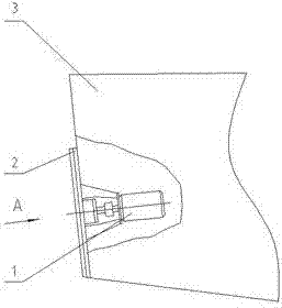
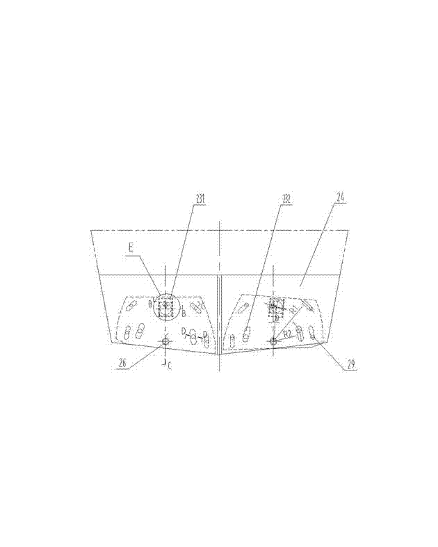
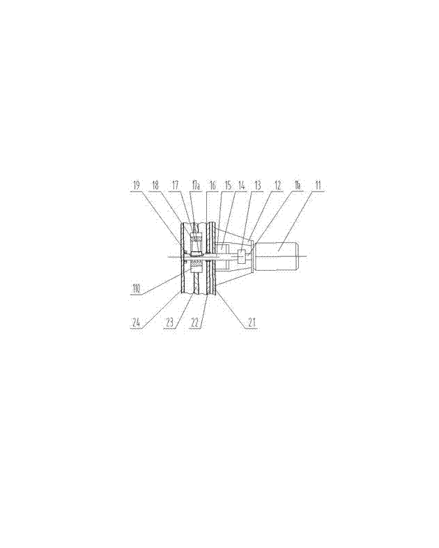
[0021] Such as Figure 1 to Figure 8 As shown, this embodiment includes two sets of drive mechanisms 1 and two sets of actuators 2, the drive mechanism 1 is symmetrically arranged on both sides of the speedboat stern 3, the actuator 2 is symmetrically arranged on the outer sides of the speedboat stern 3, and the actuator 1 Connect with drive mechanism 2. The driving mechanism 1 includes a stepping motor 11, a driving shaft 15, an eccentric wheel 17, a driving slider 18 and a pair of vertical slide rails 110, and the actuator 2 includes a base plate 22, a cover plate 24, a rectifying plate 23, a spindle bearing 25, Mandrel 26, several anti-warping pins 27, several pairs of vertical slide rails 211, several end surface sliders 27 and several pairs of smooth rails 28. The power source of the driving mechanism 1 is a stepper motor 11, and the stepper motor 11 is fixed on ...


PUM


Abstract

The invention discloses a double-plate swirling rectification anti-drag stabilizer of a speed boat. The double-plate swirling rectification anti-drag stabilizer comprises two sets of driving mechanisms and two sets of executing mechanisms, wherein the two sets of driving mechanisms are respectively arranged at two sides inside the stern of a planing boat; the two sets of executing mechanisms are arranged at two sides outside the stern of the planing boat; the executing mechanisms are connected with the driving mechanisms in an embedding mode; each driving mechanism comprises a stepper motor, a sealing device, a driving shaft, an eccentric wheel and a driving slide block; each executing mechanism comprises a base plate, a cover plate, a rectifying plate, a plurality of rising prevention pins and a plurality of end surface slide blocks; the driving mechanisms drive the rectifying plates to rotate around the center of a mandrel arranged below the rectifying plates through the eccentric wheels and the driving slide blocks, so that the lower edges of the rectifying plates stretch out of the bottom edge of the planing boat to cut into water, and the problem of hydrodynamic performance defect at the bottom of the planing boat caused by design or construction can be changed. According to the double-plate swirling rectification anti-drag stabilizer, an appropriate movement combination mode of the rectifying plates can be selected according to the ocean situation and the practical situation of the shipping state of the planing boat, so that the water flow field and the hydrodynamic force pressure center at the bottom of the speed boat are changed, and thus the purposes of anti-drag and stabilization are achieved.

Description

technical field [0001] The invention relates to a drag reduction and anti-rolling device for a speedboat, in particular to a drag and anti-rolling device with two rotatable rectifying plates arranged at the stern of a boat, and belongs to the technical field of ship engineering. Background technique [0002] When speedboats (including displacement boats, transition boats, and planing boats) sail at high speed on the water surface, due to the action of wind, waves, and currents, the hull will sway significantly, which poses a threat to the safety of personnel, equipment, and boats. Especially for military boats, weapons cannot be used normally, so as to delay fighters. At present, there are many types of anti-rolling devices for ships. In summary, there are mainly the following anti-rolling methods: bilge keels, anti-rolling water tanks, and anti-rolling fins. Due to the particularity of the speedboat’s sailing state and the small displacement of the hull, except for the bi...

Claims


Application Information

Patent Timeline
Patent Type & Authority Applications(China)
IPC IPC(8): B63B39/00
Inventor 周玉龙杨超
Owner JIANGSU UNIV OF SCI & TECH
Why Eureka
Try Eureka