
Shower room chassis with chute decontamination mechanism

A shower room and chassis technology, which is applied in the field of shower room, can solve the problems such as difficult cleaning of impurities and dirt in the chute, and achieve the effect of thorough cleaning of the device

Active Publication Date: 2021-03-16
浙江艾希德新材料科技有限公司
View PDF11 Cites 0 Cited by
  • Summary
  • Abstract
  • Description
  • Claims
  • Application Information

AI Technical Summary

Problems solved by technology

[0004] Aiming at the deficiencies of the prior art, the present invention provides a shower room chassis with a chute decontamination mechanism, which solves the problem that impurities and dirt inside the chute are not easy to clean

Method used


Image

  • Shower room chassis with chute decontamination mechanism
  • Shower room chassis with chute decontamination mechanism
  • Shower room chassis with chute decontamination mechanism

Examples


Embodiment 1

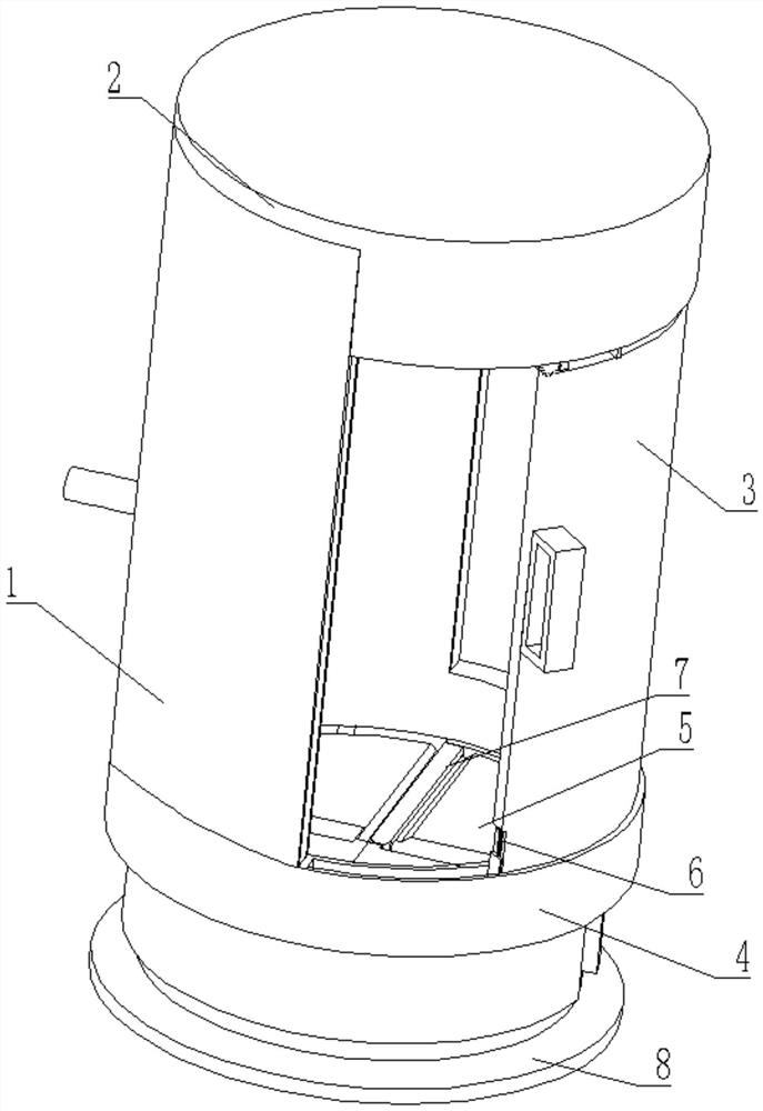
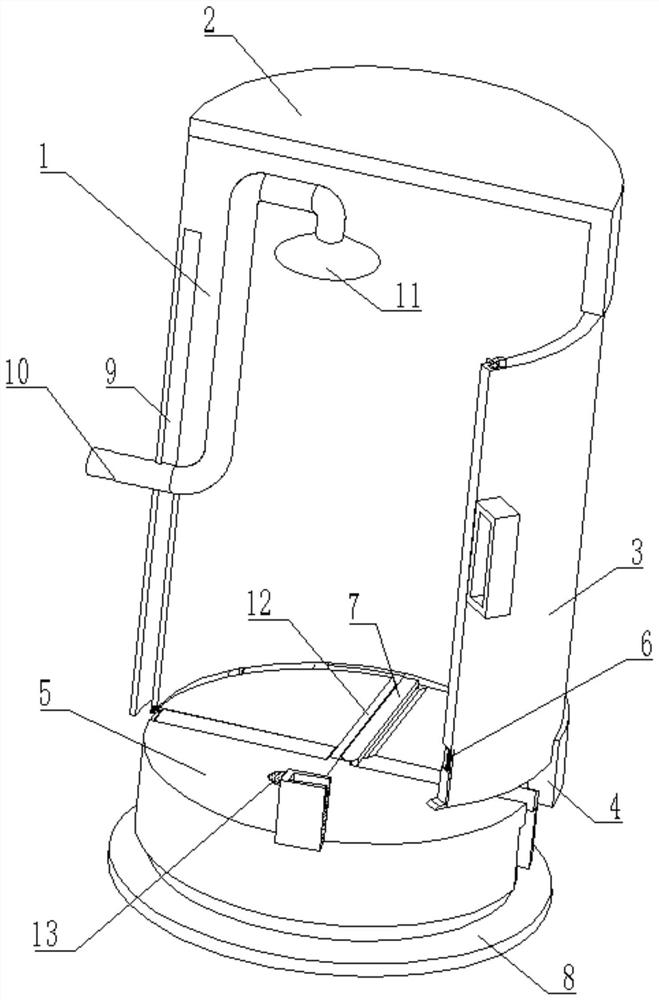
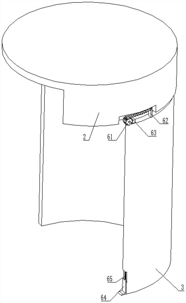
[0030] see Figure 1-6 , a shower room chassis with a chute decontamination mechanism, comprising a box body 1, the top of the box body 1 is fixedly connected with a connecting seat 2, the bottom of the box body 1 is fixedly connected with a lower plate body 4, and the inner wall of the lower plate body 4 The chassis body 5 is fixedly connected, the bottom of the chassis body 5 is provided with a rotating mechanism 8, the upper surface of the chassis body 5 is provided with a decontamination mechanism 7, the inside of the box body 1 is slidingly connected with a sliding door 3, and the inside of the sliding door 3 is provided with The cleaning mechanism 6 is fixedly connected with a water inlet pipe 10 inside the box body 1 , and a nozzle 11 is arranged inside the water inlet pipe 10 .

[0031] In this embodiment, a sliding slot 9 is opened inside the box body 1 , the sliding door 3 is located inside the sliding slot 9 , and a turning slot 12 is opened on the upper surface of ...

Embodiment 2

[0044] see Figure 6-7 On the basis of Embodiment 1, in this embodiment, the surface of the sewage pipe 775 is connected with a leaking pipe 14, and the top of the leaking pipe 14 is clamped with a floor drain 13, and the diameter of the sewage pipe 775 is larger than that of the leaking pipe 14.

[0045] The installed floor drain 13 allows shower water to flow out from the floor drain 13, and the sewage pipe 775 is used to remove the accumulation of some hair, dust and impurities to avoid blockage of the floor drain 13, and the diameter of the sewage pipe 775 is set to be larger , then it is in order to avoid the situation that the sewage pipe 775 will be blocked by hair.

[0046] In this embodiment, the rotating mechanism 8 includes a drive plate 81, the inner wall of the drive plate 81 is meshed with an intermediate gear 82, the axis of the intermediate gear 82 is connected to the bottom of the chassis body 5 through a shaft, and the surface of the intermediate gear 82 is e...


PUM


Abstract

The invention relates to the technical field of shower rooms, and discloses a shower room chassis with a chute decontamination mechanism, which comprises a box body, the top of the box body is fixedlyconnected with a connecting seat, the bottom of the box body is fixedly connected with a lower chassis body, the inner wall of the lower chassis body is fixedly connected with a chassis body, and thebottom of the chassis body is provided with a rotating mechanism. And a dirt removing mechanism is arranged on the upper surface of the chassis body, a sliding door is slidably connected into the boxbody, and a cleaning mechanism is arranged in the sliding door. According to the shower room chassis with the chute decontamination, when the sliding door is closed by controlling the sliding door tomove leftwards and slide, the cleaning plate is firstly driven to clean impurities in the sliding groove in the lower plate body, and when the cleaning plate ascends, the impurities in the sliding groove can be taken out in a sliding mode; quick cleaning of the sliding groove is achieved through push-and-pull power of the sliding door, and the problem that impurities and dirt in the sliding groove are not easy to clean manually is solved.

Description

technical field [0001] The invention relates to the technical field of shower rooms, in particular to a shower room chassis with a chute decontamination mechanism. Background technique [0002] The shower room is a separate shower compartment. Modern homes have higher and higher requirements for bathroom facilities. Many families hope to have an independent bathing space. However, due to the limited sanitary space in the living room, the bathing facilities and sanitary ware can only be placed together. room. The shower room makes full use of a corner of the room, and uses a fence to clearly divide the shower range to form a relatively independent bathing space. According to the function, the shower room is divided into integral shower room and simple shower room; according to the style, it is divided into corner shower room, one-shaped bath screen, arc-shaped shower room, bathtub upper bath screen, etc.; according to the shape of the chassis, it is divided into square and f...

Claims


Application Information

Patent Timeline
Patent Type & Authority Applications(China)
IPC IPC(8): A47K3/40E06B3/46
CPCA47K3/40E06B3/4636
Inventor 俞人炜
Owner 浙江艾希德新材料科技有限公司
Learn More