Marine cabin lighting equipment
A lighting equipment and cabin technology, applied in the field of marine cabin lighting equipment, can solve the problems of increasing workload, affecting equipment, piping installation, wasting man-hours, etc., and achieving the effect of realizing the angle
- Summary
- Abstract
- Description
- Claims
- Application Information
AI Technical Summary
Problems solved by technology
Method used
Image

Examples
Embodiment Construction
[0019] The technical solution of the present invention is further described below in conjunction with specific embodiments:
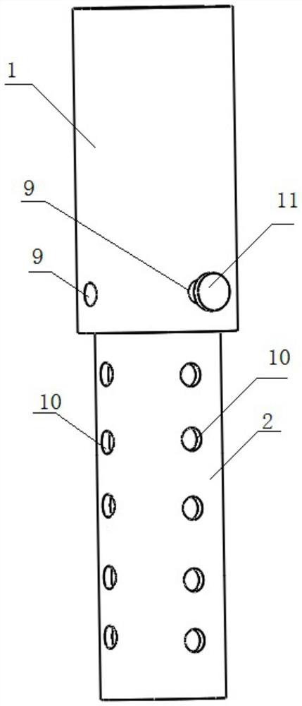
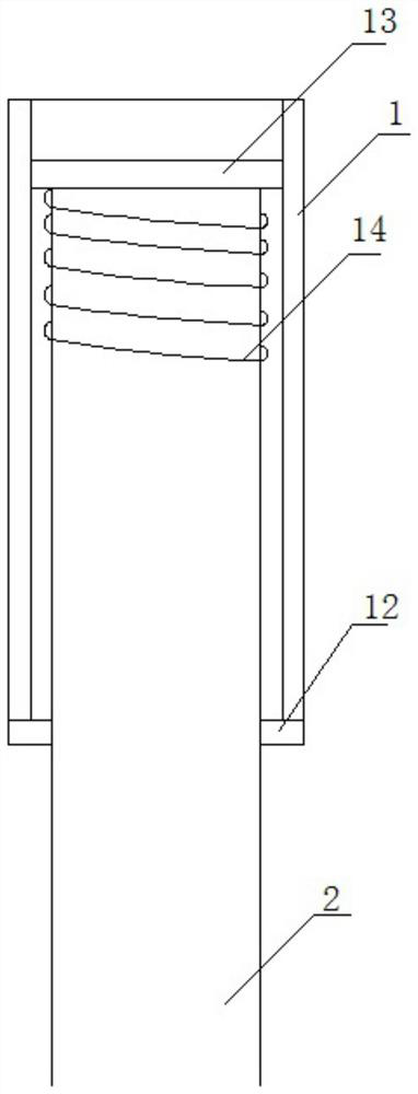
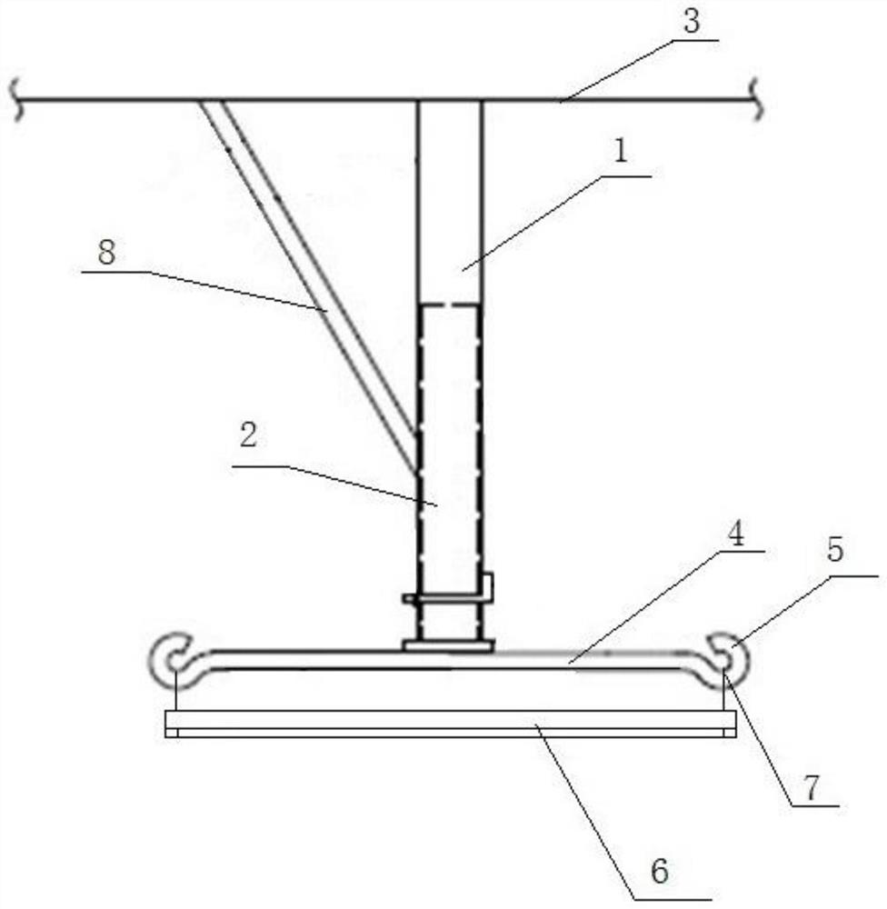
[0020] A marine cabin lighting device, such as Figure 1-2 As shown, it includes a fixed base 1, a movable base 2, an installation base, and a lighting device. The lower end of the fixed base 1 is a tubular structure, and steel pipes can be used directly. The upper end of the movable base 2 is inserted into the fixed base 1 from the lower end of the fixed base 1 by welding and fixed on the reverse top 3 of the cabin; The lower end is vertically fixed on the middle part of the crossbeam 4, and a suspension device 5 is provided at both ends of the crossbeam 4 respectively; The hanging lugs at the two ends of the shaped lamp tube 6 are respectively suspended on the suspension device 5 at the two ends of the crossbeam 4, and then the lighting device is installed on the lower end of the installation base; The anti-top 3 is welded and fixed, and the other e...
PUM
 Abstract
Description
Claims
Application Information