Casing pressure transit time method material level instrument

A technology of transit time and material level, which is applied in directions such as buoy liquid level indicators, and can solve problems such as measurement data deviations

Inactive Publication Date: 2021-03-16
泉州市启明电子设备有限公司
View PDF0 Cites 1 Cited by
  • Summary
  • Abstract
  • Description
  • Claims
  • Application Information

AI Technical Summary

Problems solved by technology

[0003] Since the casing pressure transit time method level instrument measures the liquid level height through the floating of the internal float, if the water level is measured in the natural canal water, there will be tiny duckweed in the canal water when the measuring rod is extended into the canal water. together into the measuring rod, so that the duckweed will float on the water surface in the measuring rod, so the floating ball will be supported upwards, so that the measurement data of the casing pressure transit time method level instrument will be deviated

Method used


Image

  • Casing pressure transit time method material level instrument
  • Casing pressure transit time method material level instrument
  • Casing pressure transit time method material level instrument

Examples


Embodiment 1

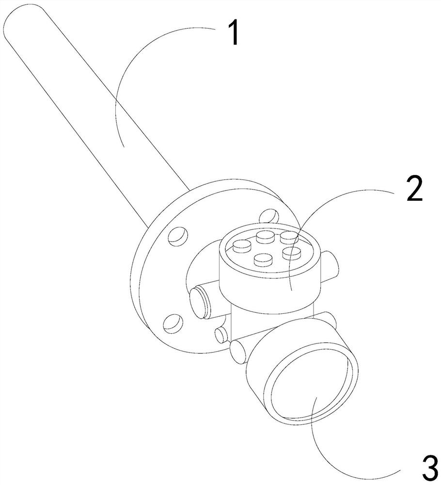
[0026] For example figure 1 -example Figure 5 Shown:

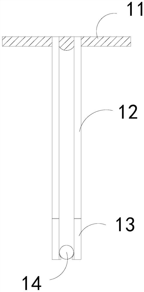
[0027] The present invention provides a casing pressure transit time method material level instrument, its structure includes a measuring rod 1, a handle 2, and a display screen 3, the display screen 3 is embedded in the front end of the handle 2, and the measuring rod 1 is installed on The rear end position of the handle 2; the measuring rod 1 includes an engaging plate 11, a rod body 12, an outer row mechanism 13, and a floating ball 14, and the rod body 12 is embedded in the inner center position of the connecting plate 11, and the outer row mechanism 13 and The rod body 12 is an integrated structure, and the floating ball 14 is installed at the inner position of the rod body 12 and the outer row mechanism 13 .

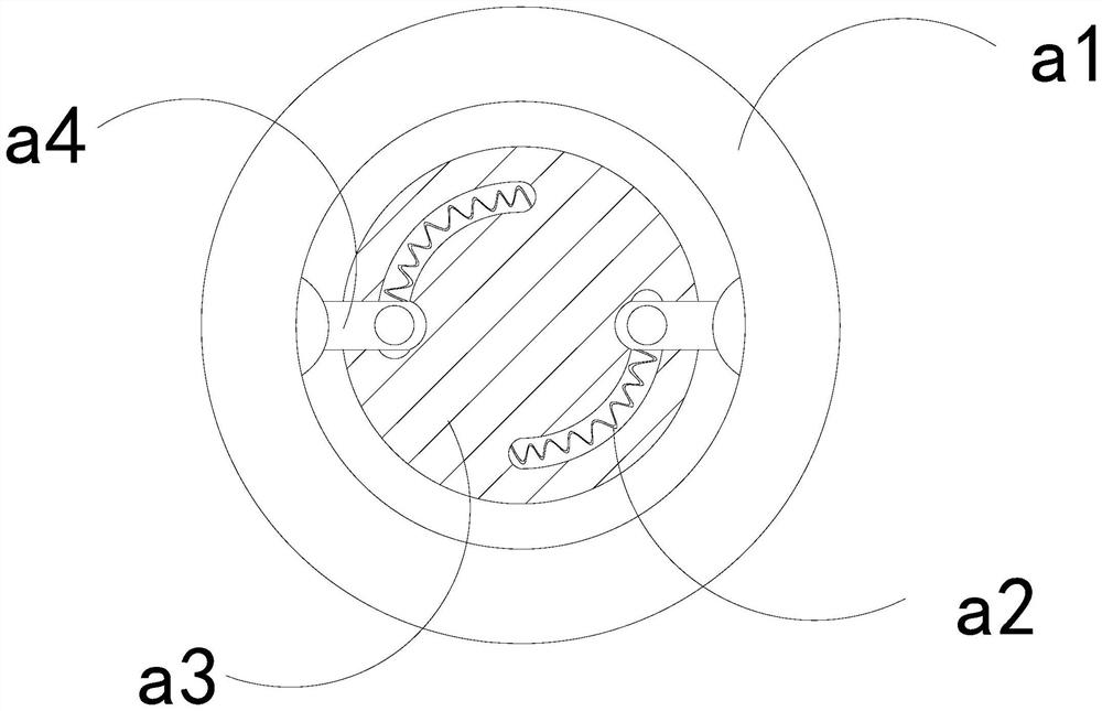
[0028] Wherein, the floating ball 14 includes a stressed ring a1, an elastic strip a2, a fixed block a3, and a coupling rod a4, the stressed ring a1 is movably engaged with the fixed block a3 through the cou...

Embodiment 2

[0034] For example Figure 6 -example Figure 8 Shown:

[0035] Wherein, the outer discharge mechanism 13 includes a frame c1, a discharge block c2, a squeeze ball c3, and a booster bar c4. The discharge block c2 is embedded in the bottom position of the inner wall of the frame c1, and the squeeze ball c3 passes The booster bar c4 is connected to the upper end of the inner wall of the frame c1. There are two extrusion balls c3, which are evenly distributed symmetrically inside the frame c1. Duckweed presses down.

[0036] Wherein, the discharge block c2 includes a stressed roller c21, a plate c22, a direction limiting block c23, and a connecting plate c24. The stressed roller c21 is movably engaged with the connecting plate c24. In the middle position of c21, the connecting plate c24 is embedded and connected with the plate c22, and the water can generate a downward thrust on the force-bearing roller c21, which can make the force-bearing roller c21 rotate clockwise, and the...


PUM


Abstract

The invention discloses a casing pressure transit time method material level instrument which structurally comprises a measuring rod, a handle and a display screen, the display screen is fixedly embedded in the front end of the handle, the measuring rod is installed at the rear end of the handle, upward thrust is generated on a stress ring through canal water, and the stress ring can rotate clockwise along a fixing block under cooperation of a combination rod. The swing plate can be matched with the grabbing block to grab duckweed on water in a canal entering the measuring rod and then drive the duckweed upwards, so that the measuring rod can measure accurate water level height data, the duckweed and water between the floating ball and the discharging mechanism can be brought into the frame through the opening in the inner side of the frame, and through water and thrust generated by duckweed to the stress roller, the water can extrude the outer contact plate, so that the outer contactplate can contract inwards, and the water can drive the duckweed to be extruded downwards between the outer contact plate and the inner wall of the plate.

Description

technical field [0001] The invention relates to the field of level instruments and meters, in particular to a level meter with a casing pressure transit time method. Background technique [0002] The casing pressure transit time method level meter is mainly used to measure the liquid level of the liquid. By fully extending the measuring rod at the bottom of the casing pressure transit time method level meter into the water to be measured, the inside of the measuring rod The float can float, so that the display screen of the casing pressure transit time method level instrument can intuitively reflect the measured data. Based on the above description, the inventors found that an existing casing pressure transit time method The position meter mainly has the following deficiencies, for example: [0003] Since the casing pressure transit time method level instrument measures the liquid level height through the floating of the internal float, if the water level is measured in the...

Claims


Application Information

Patent Timeline
Patent Type & Authority Applications(China)
IPC IPC(8): G01F23/56
CPCG01F23/56
Inventor 叶贤良
Owner 泉州市启明电子设备有限公司
Why Eureka
Try Eureka