Optical system, camera module and terminal equipment

An optical system and optical axis technology, applied in optics, optical components, instruments, etc., can solve the problems of large screen opening, large lens thickness ratio, difficult lens molding, etc., to improve the molding yield and reduce the possibility of the effect.

Pending Publication Date: 2021-03-16
JIANGXI JINGCHAO OPTICAL CO LTD
View PDF0 Cites 2 Cited by
  • Summary
  • Abstract
  • Description
  • Claims
  • Application Information

AI Technical Summary

Problems solved by technology

[0003] At present, the size of the optical system tends to be miniaturized and thinner under the market trend, but the head of the optical system is large, which is not conducive to the packaging of the optical system under the screen, and the screen has a large opening
In addition, the thickness ratio of the lens is usually large, making lens molding difficult

Method used


Image

  • Optical system, camera module and terminal equipment
  • Optical system, camera module and terminal equipment
  • Optical system, camera module and terminal equipment

Examples


Embodiment 1

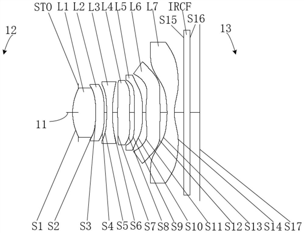
[0054] like figure 1 As shown, the straight line 11 represents the optical axis, the side of the first lens L1 away from the second lens L2 is the object side 12 , and the side of the seventh lens L7 away from the sixth lens L6 is the image side 13 . In the optical system provided by this embodiment, from the object side 12 to the image side 13 are the diaphragm STO, the first lens L1, the second lens L2, the third lens L3, the fourth lens L4, the fifth lens L5, the Six lenses L6, a seventh lens L7, and an infrared filter element IRCF.

[0055] The first lens L1 has a positive refractive power and is made of plastic material. Its object side S1 is convex at the near optical axis and at the circumference, and its image side S2 is convex at the near optical axis and at the circumference. sphere.

[0056] The second lens L2 has negative refractive power and is made of plastic material. Its object side S3 is concave at the near optical axis and at the circumference, and its imag...

Embodiment 2

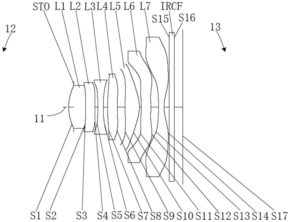
[0078] like image 3 As shown, the straight line 11 represents the optical axis, the side of the first lens L1 away from the second lens L2 is the object side 12 , and the side of the seventh lens L7 away from the sixth lens L6 is the image side 13 . In the optical system provided by this embodiment, from the object side 12 to the image side 13 are the diaphragm STO, the first lens L1, the second lens L2, the third lens L3, the fourth lens L4, the fifth lens L5, the Six lenses L6, a seventh lens L7, and an infrared filter element IRCF.

[0079] The first lens L1 has positive refractive power and is made of plastic material. Its object side S1 is convex at the near optical axis and at the circumference, its image side S2 is concave at the near optical axis, and its image side S2 is at the near optical axis. It is convex at the center and at the circumference, and both are aspherical.

[0080] The second lens L2 has negative refractive power and is made of plastic material. It...

Embodiment 3

[0098] like Figure 5 As shown, the straight line 11 represents the optical axis, the side of the first lens L1 away from the second lens L2 is the object side 12 , and the side of the seventh lens L7 away from the sixth lens L6 is the image side 13 . In the optical system provided by this embodiment, from the object side 12 to the image side 13 are the diaphragm STO, the first lens L1, the second lens L2, the third lens L3, the fourth lens L4, the fifth lens L5, the Six lenses L6, a seventh lens L7, and an infrared filter element IRCF.

[0099]The first lens L1 has a positive refractive power and is made of plastic material. Its object side S1 is convex at the near optical axis and at the circumference, and its image side S2 is convex at the near optical axis and at the circumference. sphere.

[0100] The second lens L2 has negative refractive power and is made of plastic material. Its object side S3 is concave at the near optical axis and at the circumference, its image si...


PUM


Abstract

The embodiment of the invention discloses an optical system, a camera module and terminal equipment. The optical system comprises a first lens and a fifth lens which have positive refraction power, asecond lens and a seventh lens which have negative refraction power, and a third lens, a fourth lens and a sixth lens which have refraction power. The object side face of the first lens is convex at aparaxial region, the image side face of the fourth lens is concave at a paraxial region, the object side surface and the image side surface of the fifth lens are convex at a paraxial region, the image side surface of the sixth lens is convex at a paraxial region, and the image side surface of the seventh lens is concave at a paraxial region. The image side surface of the first lens and the objectside surface of the second lens are glued. By reasonably configuring the refractive power and the surface type of the first lens to the seventh lens in the optical system and limiting the first lensand the second lens to be glued, the optical system can achieve the characteristics of miniaturization and small head, and the forming yield of the lens is improved.

Description

technical field [0001] The present application belongs to the technical field of optical imaging, and in particular relates to an optical system, a camera module and a terminal device. Background technique [0002] In recent years, with the rapid development of manufacturing technologies for electronic products such as smartphones, tablets, and cameras, and the emergence of increasingly diversified user needs, the market's requirements for optical systems have become increasingly demanding. [0003] At present, the size of the optical system tends to be miniaturized and thinner under the market trend, but the head of the optical system is relatively large, which is not conducive to the packaging of the optical system under the screen, and the screen has a large opening. In addition, the thickness ratio of the lens is usually large, making lens molding difficult. [0004] Therefore, how to improve the molding yield of the lens and realize the miniaturization of the optical s...

Claims


Application Information

Patent Timeline
Patent Type & Authority Applications(China)
IPC IPC(8): G02B13/00G02B13/18
CPCG02B13/0015G02B13/0045G02B13/006
Inventor 谭怡翔李明刘秀
Owner JIANGXI JINGCHAO OPTICAL CO LTD
Why Eureka
Try Eureka