

Electromagnetic relay with clamping structure
A technology of electromagnetic relays and relays, applied in the direction of electromagnetic relays, electromagnetic relay details, relays, etc., can solve problems such as damaged solder joints, damaged welding parts, poor welding, etc., to achieve less damage, increased flexibility, and easy deformation Effect
- Summary
- Abstract
- Description
- Claims
- Application Information
AI Technical Summary
Problems solved by technology
Method used
Image

Examples
Embodiment Construction
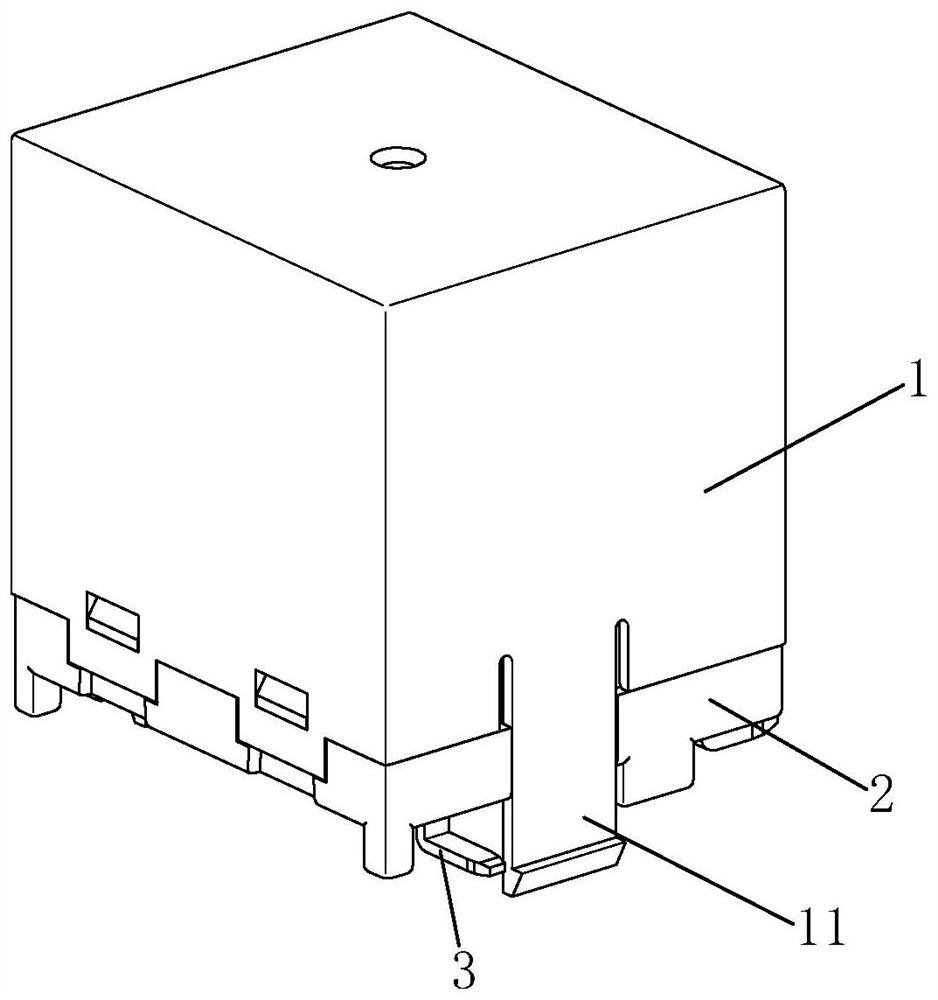
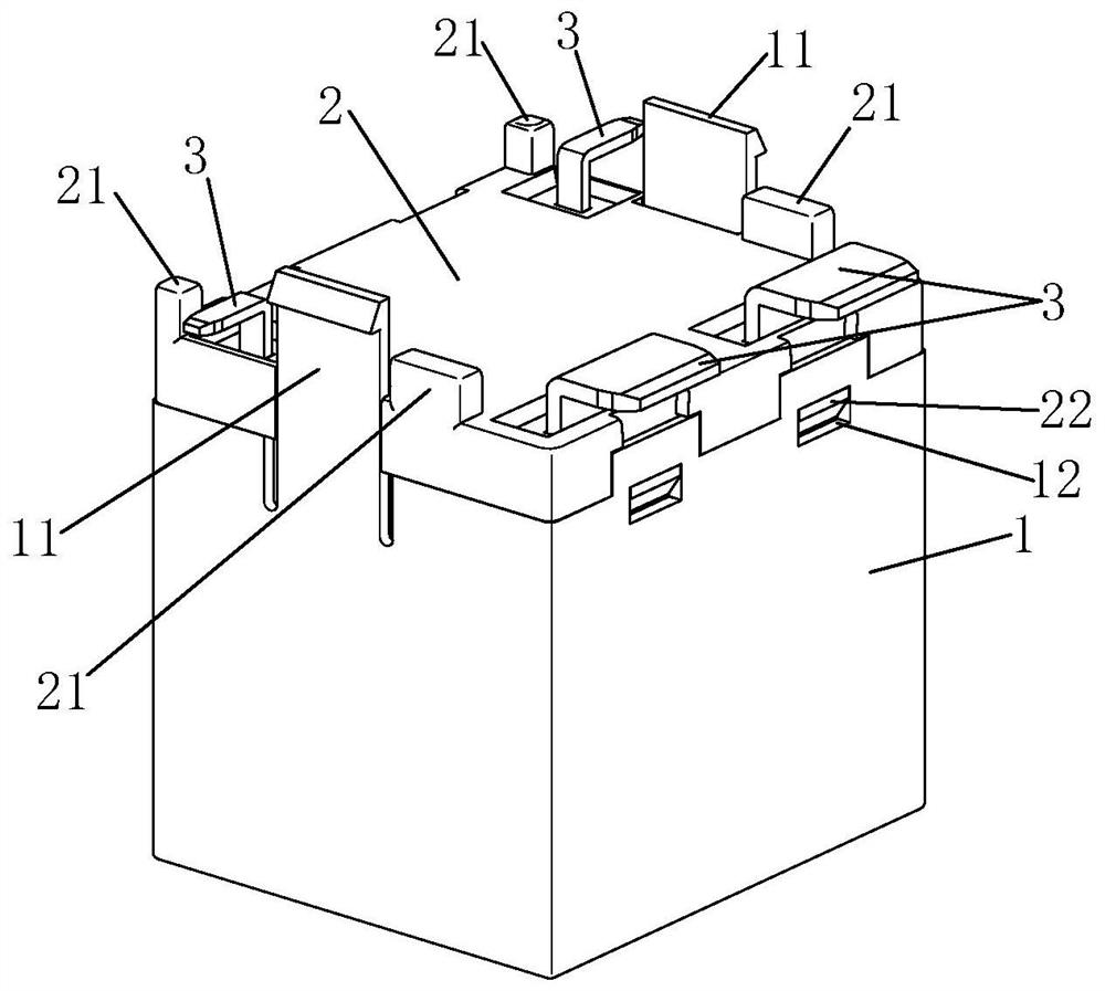
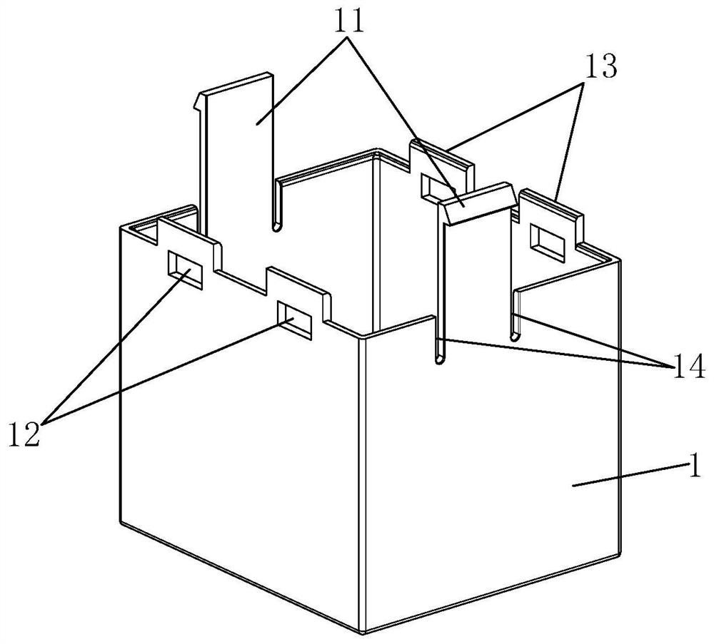
[0028] Examples, see Figure 1-Figure 7 As shown, an electromagnetic relay with a clamping structure of the present invention includes a relay body, a magnetic circuit part (not shown in the figure) and a contact part (not shown in the figure) located in the relay body, and the bottom of the relay body has a The surface is mounted on several lead-out pins 3 of the PCB board or the substrate; several buckles 11 are arranged at the bottom of the relay body, and each buckle 11 is used to be fastened on the PCB board or the substrate respectively. The substrate refers to various boards other than the PCB board that can surface mount the electromagnetic relay.
[0029] In this embodiment, the relay body includes a base 2 and a casing 1 with an open bottom, and the bottom of the casing 1 is connected to the base 2; the several lead-out pins 3 are respectively the lead-out pins of the magnetic circuit part or the contact parts. Lead-out pins, each lead-out pin passes through the thr...
PUM
 Abstract
Description
Claims
Application Information