
Control method for expanding operation range of three-phase cascaded H-bridge inverter

A control method and technology of operating range, applied in the control field of expanding the operating range of a three-phase cascaded H-bridge inverter, can solve the problem of affecting MPPT efficiency, unable to cope with power imbalance, and increasing the DC side capacitor voltage of the H-bridge converter volatility etc.

Active Publication Date: 2021-03-16
HEFEI UNIV OF TECH
View PDF10 Cites 0 Cited by
  • Summary
  • Abstract
  • Description
  • Claims
  • Application Information

AI Technical Summary

Problems solved by technology

[0010] 1) Hybrid modulation can expand the linear modulation range of the H-bridge converter to 4 / π, but it will increase the voltage fluctuation of the DC side capacitor of the H-bridge converter and affect the efficiency of MPPT
[0011] 3) The third harmonic compensation strategy will not aggravate the voltage fluctuation of the DC side capacitor of the H-bridge converter, and improve the linear modulation range of the H-bridge converter to 1.155, but its ability to deal with power imbalance is still weak and cannot cope with more severe power imbalance

Method used


Image

  • Control method for expanding operation range of three-phase cascaded H-bridge inverter
  • Control method for expanding operation range of three-phase cascaded H-bridge inverter
  • Control method for expanding operation range of three-phase cascaded H-bridge inverter

Examples


Embodiment Construction

[0092] In order to make the objectives, technical solutions and advantages of the present invention more clear, the present invention will be further clearly and completely described below with reference to the accompanying drawings and embodiments.

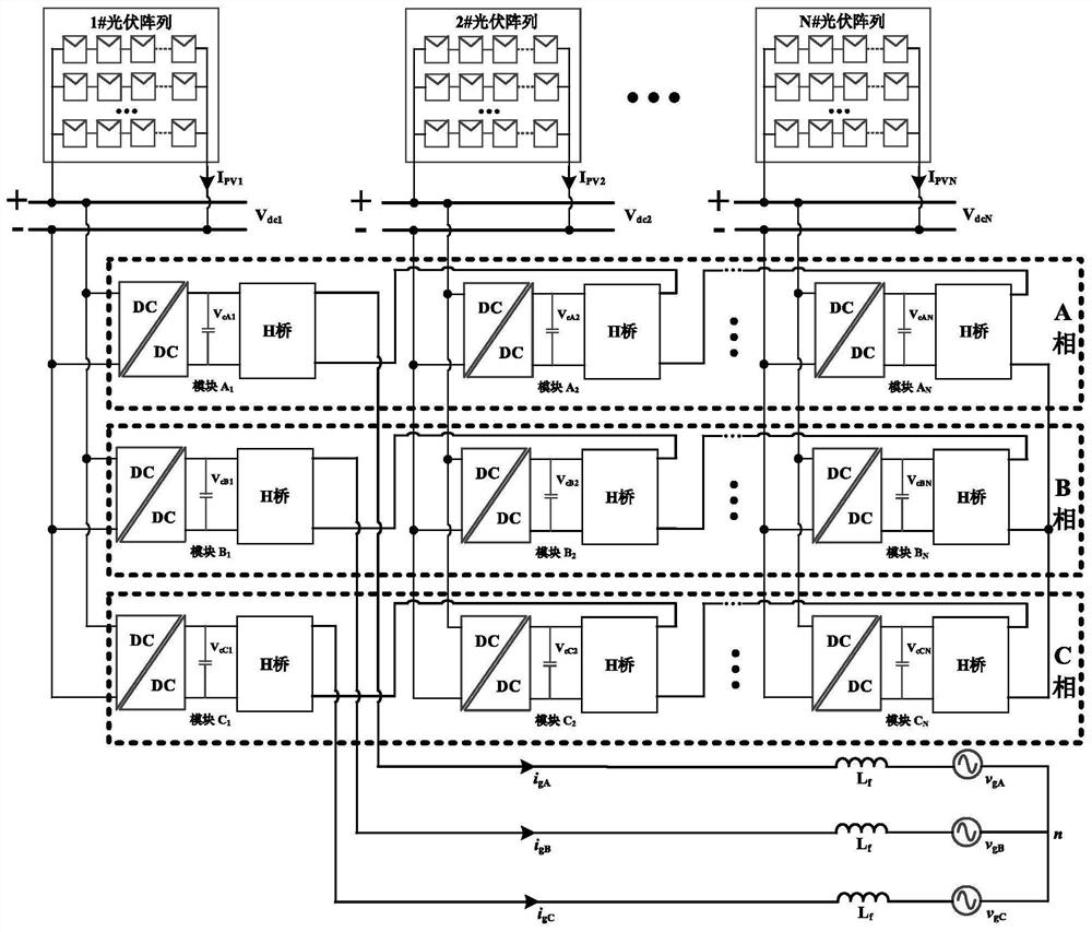
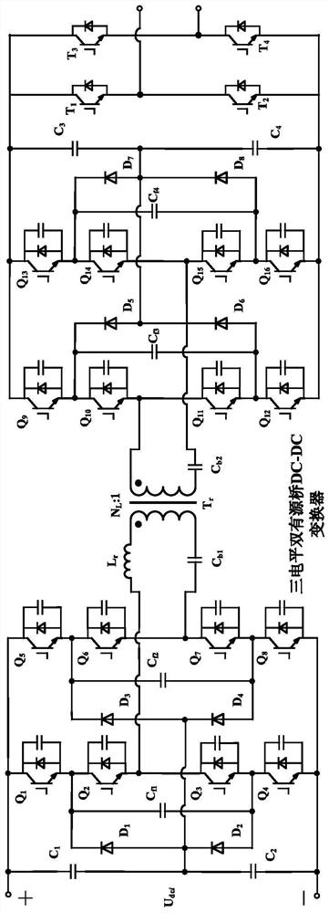
[0093] figure 1 It is the main circuit topology structure of the three-phase cascaded H-bridge inverter implemented in the present invention. It can be seen from this figure that the three-phase cascaded H-bridge inverter is composed of A phase, B phase and C phase. Phase A, Phase B, and Phase C each include N modules, where N is a positive integer greater than 1, and all modules in Phase A, Phase B, and Phase C have the same structure. All modules in Phase A, Phase B and Phase C consist of a three-level full-bridge DAB converter in series with an H-bridge converter. The input ports of the i-th modules in the A-phase, B-phase and C-phase which are respectively set and corresponding to each other are connected in parallel to form...


PUM


Abstract

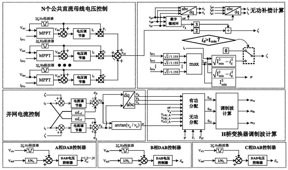
The invention discloses a control method for expanding the operation range of a three-phase cascaded H-bridge inverter, and aims to solve the problem of power imbalance of the three-phase cascaded H-bridge inverter. The method mainly comprises the following steps: (1) controlling the voltage of each direct-current bus in the three-phase cascaded H-bridge inverter to enable a photovoltaic array corresponding to each common direct-current bus to work at a maximum power point, and obtaining an active power value transmitted by the corresponding common direct-current bus; (2) calculating a grid-connected current reactive component reference value; (3) calculating a grid-connected current active component reference value and controlling the grid-connected current in combination with the grid-connected current reactive component reference value obtained in the previous step; and (4) distributing the three-phase total active modulation voltage and the three-phase total reactive modulation voltage obtained in the previous step, calculating the total modulation degree of each H-bridge converter, and injecting third harmonics to obtain the modulation wave of each H-bridge converter. Comparedwith the prior art, the linear modulation range of the three-phase cascaded H-bridge inverter is further expanded, and the capacity of the three-phase cascaded H-bridge inverter for coping with powerimbalance is improved.

Description

technical field [0001] The invention belongs to the photovoltaic power generation technology in the field of electrical engineering, and particularly relates to a control method for expanding the operating range of a three-phase cascaded H-bridge inverter. Background technique [0002] In high-voltage and high-power photovoltaic systems, traditional centralized inverters are limited by semiconductor switching devices, and it is difficult to further increase the rated power. At the same time, in order to realize the medium voltage grid connection, the traditional centralized inverter needs a bulky power frequency transformer, which increases the volume of the inverter. To solve these problems, one of the methods is to use a three-phase cascaded H-bridge inverter. The modular structure design can use common low-voltage switching devices to achieve higher output voltage, improve the power level of the inverter, and avoid the use of power frequency transformers. High-frequency...

Claims


Application Information

Patent Timeline
IPC IPC(8): H02J3/38H02J3/26H02J3/01H02M7/49H02M7/5387
CPCH02J3/38H02J3/26H02J3/01H02M7/49H02M7/53871H02J2300/26Y02E10/56Y02E40/40Y02E40/50
Inventor 张兴王明达吴孟泽郭梓暄王付胜
Owner HEFEI UNIV OF TECH
Learn More