
Constant temperature and moisture test box

A constant temperature and humidity test and test chamber technology, applied in the field of test chambers, can solve the problems of uneven distribution of air temperature and humidity, large size, and bulkiness, and achieve the effect of reducing the mutual influence of temperature and humidity

Inactive Publication Date: 2021-03-19
无锡市恒升试验设备有限公司
View PDF0 Cites 2 Cited by
  • Summary
  • Abstract
  • Description
  • Claims
  • Application Information

AI Technical Summary

Problems solved by technology

However, because the air is not mixed evenly before being discharged into the test chamber, the air temperature and humidity in the test chamber will be unevenly distributed after being discharged into the test chamber, which will affect the test results.
Moreover, most of the existing high and low temperature test chambers adopt a horizontal structure, which is large in size and heavy, and the entrance of most laboratories is small, which makes the transportation and installation process very inconvenient
At the same time, there is no over-temperature protection for heat preservation and temperature changes during the temperature adjustment process. During the temperature change, the constant humidity cannot be adjusted, resulting in an imbalance in the overall temperature and humidity adjustment.

Method used


Image

  • Constant temperature and moisture test box
  • Constant temperature and moisture test box

Examples


Embodiment Construction

[0017] The following will clearly and completely describe the technical solutions in the embodiments of the present invention with reference to the accompanying drawings in the embodiments of the present invention. Obviously, the described embodiments are only some, not all, embodiments of the present invention.

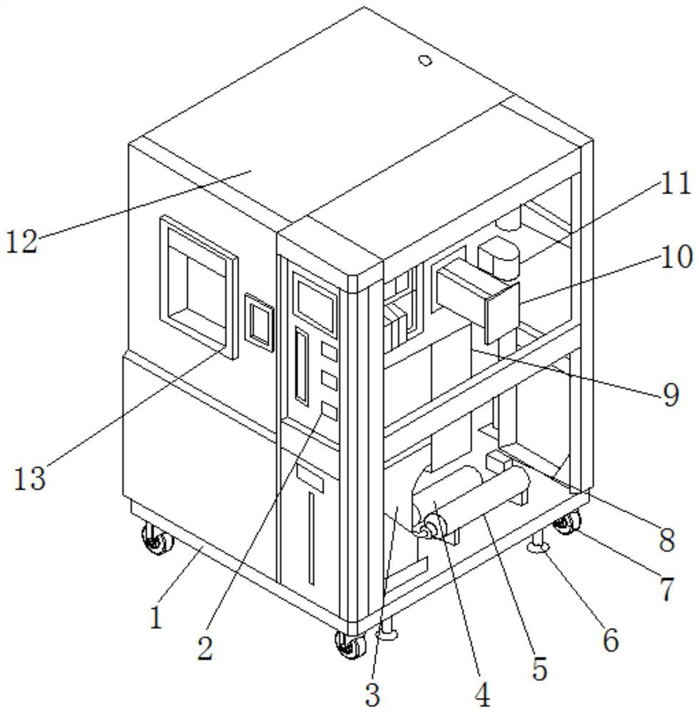
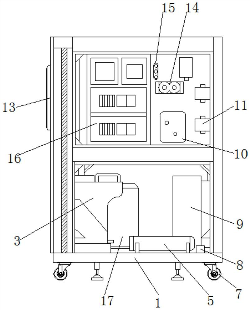
[0018] refer to Figure 1-2 , a constant temperature and humidity test chamber, comprising a bottom plate 1, a cabinet body 12 is welded on the top outer wall of the bottom plate 1, and a test chamber and an accessory chamber are arranged on one side outer wall of the cabinet body 12, and an experiment chamber is arranged on one side outer wall of the cabinet body 12. The chamber 13, and the outer wall of the experiment chamber 13 is fixed with a hermetic door through hinges, the side of the cabinet body 12 close to the experiment chamber 13 is provided with a control cabinet 2, and the inner wall of the experiment chamber is provided with a humidification box 10, a c...


PUM


Abstract

The invention discloses a constant temperature and moisture test box, comprising a bottom plate, wherein a cabinet body is welded to the outer wall of the top of the bottom plate; a test bin and an accessory bin are arranged on the outer wall of one side of the cabinet body; an experiment bin is arranged on the outer wall of one side of the cabinet body; a sealing door is fixed to the outer wall of the experiment bin through hinges; a control cabinet is arranged on the side, close to the experiment bin; and a humidifying box, a water cup group, an EZO over-temperature protection element and aswitchboard are arranged on the inner wall of the test bin. According to the invention, through the EZO over-temperature protection element and temperature and moisture sensors, a temperature controlarea and a moisture control area are changed separately; meanwhile, mutual influence of temperature and moisture is reduced in the temperature and moisture changing process, and constant-temperature water mist is formed in the internal water cup group; and when the water cup group works, entered to-be-atomized liquid is atomized and quantified, the temperature of an overall atomized substance is regulated and controlled, and the temperature and moisture of the water mist injected into the experiment bin reach a constant standard, so constant-temperature and constant-moisture effects are achieved.

Description

technical field [0001] The invention relates to the technical field of test chambers, in particular to a constant temperature and humidity test chamber. Background technique [0002] The working process of the existing high and low temperature test chamber is as follows: after the air is adjusted in temperature and humidity, it is directly discharged into the test chamber through a rotating fan. However, because the air is not mixed evenly before being discharged into the test chamber, the air temperature and humidity in the test chamber will be unevenly distributed after being discharged into the test chamber, which will affect the test results. Moreover, most of the existing high and low temperature test chambers adopt a horizontal structure, which is large in size and heavy, and the entrance of most laboratories is small, which makes the transportation and installation process very inconvenient. At the same time, there is no over-temperature protection for heat preservat...

Claims


Application Information

Patent Timeline
Patent Type & Authority Applications(China)
IPC IPC(8): B01L1/00B01L7/00
CPCB01L1/00B01L7/00
Inventor 张从举
Owner 无锡市恒升试验设备有限公司
Learn More