
fixture

A fixture and clamping structure technology, which is applied in the direction of chucks, manufacturing tools, manipulators, etc., can solve the problems of low suitability of fixtures and inability to meet the needs of workers, and achieve the effect of improving versatility and expanding the scope of use

Active Publication Date: 2022-05-27
ZHUHAI GREE INTELLIGENT EQUIP CO LTD +1
View PDF0 Cites 0 Cited by
  • Summary
  • Abstract
  • Description
  • Claims
  • Application Information

AI Technical Summary

Problems solved by technology

[0003] The main purpose of the present invention is to provide a clamp to solve the problem that the clamps in the prior art have low adaptability and cannot meet the needs of workers

Method used


Image

  • fixture
  • fixture
  • fixture

Examples


Embodiment 2

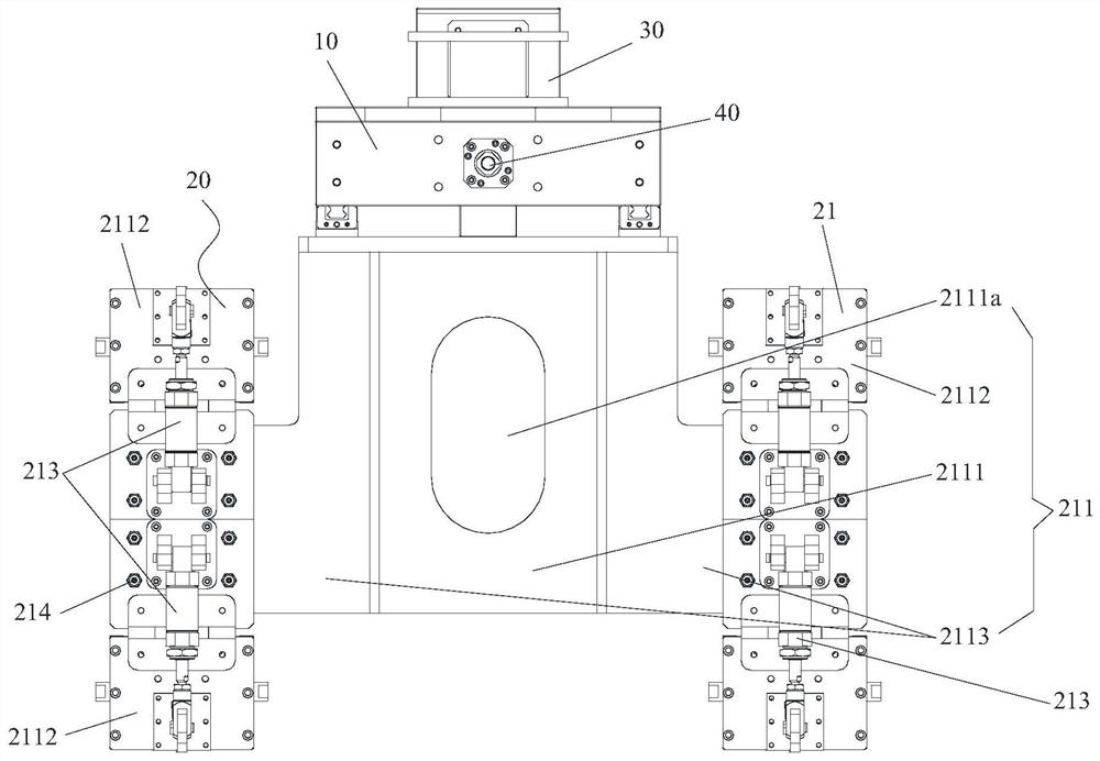
[0051] The difference between the clamp in the second embodiment and the first embodiment is that the number of the driving structures 213 is different.

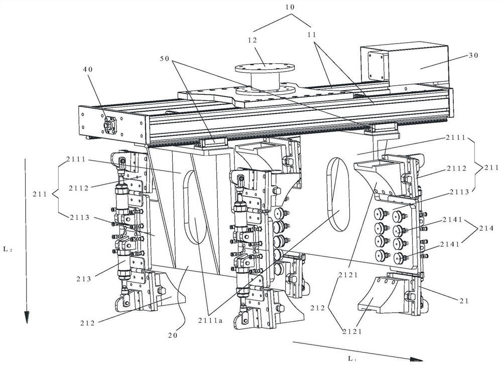
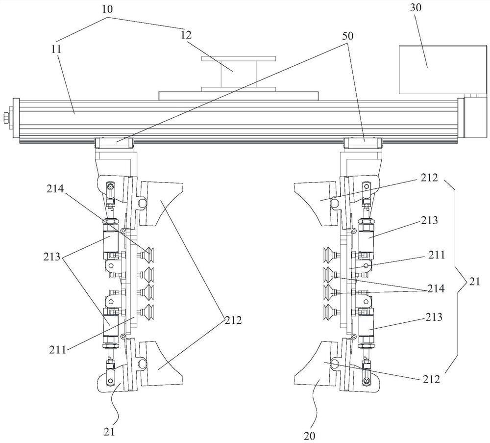
[0052] Optionally, the plurality of clamping structures include a plurality of clamping structure groups, and the plurality of clamping structure groups are along the length direction L of the mounting structure. 1 The clamping structure groups are arranged at intervals, and each clamping structure group includes two sub-clamping structures arranged oppositely. Wherein, there are multiple driving structures, and the multiple driving structures are provided in a one-to-one correspondence with the multiple clamping structure groups. Specifically, the two sub-clamping structures in each clamping structure group are along the height direction L of the mounting body 2 They are arranged at intervals, and each driving structure drives its corresponding clamping structure group to move, so that each clamping structure group moves i...


PUM


Abstract

The invention provides a clamp. The fixture includes: a frame; a clamping assembly, which is movably arranged on the frame, and the clamping assembly includes two sub-clamping assemblies oppositely arranged, and a clamping space is formed between the two sub-clamping components, and the size of the clamping space can be adjusted Adjustably arranged; wherein, each sub-clamping assembly includes: a mounting structure, which is movably arranged on the frame; a plurality of clamping structures, which are disposed on the mounting structure, and at least part of the clamping structures are pivotably connected to the mounting structure , the surface of each clamping structure facing the clamping space is an arc surface; the driving structure is drivingly connected with at least part of the clamping structure to drive the part of the clamping structure to rotate relative to the mounting structure; the suction structure is arranged on the mounting structure Structurally located between at least two clamping structures. The invention effectively solves the problem that the clips in the prior art have low adaptability and cannot meet the use needs of workers.

Description

technical field [0001] The present invention relates to the technical field of clamps, in particular to a clamp. Background technique [0002] At present, two different clamps are required for clamping the cylindrical material and the prismatic material respectively. Therefore, the adaptability of the clamp in the prior art is low and cannot be compatible with two shapes of materials, which not only increases the production cost of the clamp, but also increases the storage cost and floor space of the clamp. SUMMARY OF THE INVENTION [0003] The main purpose of the present invention is to provide a clamp to solve the problem that the adaptability of the clamp in the prior art is low and cannot meet the needs of the staff. [0004] In order to achieve the above object, the present invention provides a clamp, comprising: a frame; a clamping assembly movably arranged on the frame, the clamping assembly including two oppositely arranged sub-clamping assemblies, one of the two ...

Claims


Application Information

Patent Timeline
Patent Type & Authority Patents(China)
IPC IPC(8): B25J15/00B25J15/02B25J15/06
CPCB25J15/0052B25J15/02B25J15/0616
Inventor 章誉骞邢旭昇王健余建辉刘超
Owner ZHUHAI GREE INTELLIGENT EQUIP CO LTD
Learn More