
Bending device

A technology of bending device and bending mechanism, which is applied in the field of mechanical processing, and can solve problems such as unsuitable plate materials and limited application range

Pending Publication Date: 2021-03-23
ANHUI POLYTECHNIC UNIV MECHANICAL & ELECTRICAL COLLEGE
View PDF8 Cites 0 Cited by
  • Summary
  • Abstract
  • Description
  • Claims
  • Application Information

AI Technical Summary

Problems solved by technology

This kind of bending device can bend steel wires into bending parts with different arc shapes. It is easy to operate and has high bending efficiency, but it is not suitable for bending plate materials, and can only bend workpieces into arc shapes. Bending, the scope of application is limited

Method used


Image

  • Bending device
  • Bending device
  • Bending device

Examples


Embodiment Construction

[0026] Specific embodiments of the present invention will be described in detail below in conjunction with the accompanying drawings. It should be understood that the specific embodiments described here are only used to illustrate and explain the present invention, and are not intended to limit the present invention.

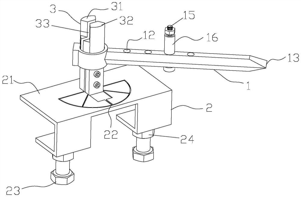
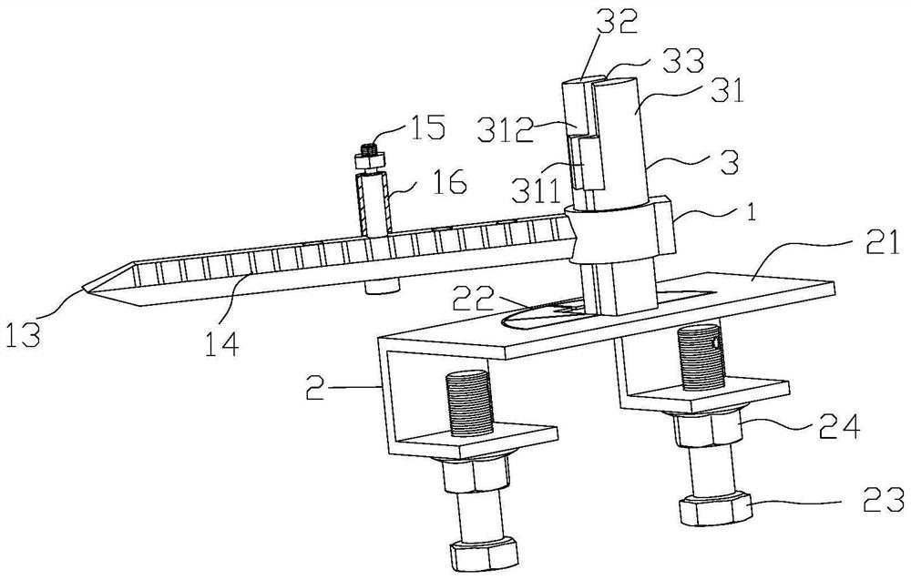
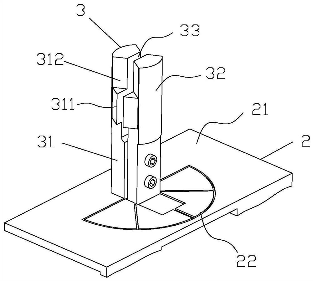
[0027] Such as Figure 1-4 As shown: the present invention provides a bending device, the bending device includes a fixing mechanism 2, a clamping mechanism 3 and a bending mechanism 1; A rod 31, a moving rod 32 movably arranged on the fixing mechanism 2, a clamping cavity 33 is formed between the fixed rod 31 and the moving rod 32, so that the moving rod 32 can approach or move away from the moving rod 32 The fixed rod 31; the bending mechanism 1 includes a rod body and a collar 11 fixed at the end of the rod body, and the collar 11 is sleeved on the clamping mechanism 3, so that the rod body can be The shaft of the clamping mechanism 3 rotates in a horizonta...


PUM


Abstract

The invention discloses a bending device. The bending device comprises a fixing mechanism, a clamping mechanism and a bending mechanism, wherein the clamping mechanism comprises a fixed rod fixed on the fixing mechanism and a movable rod movably arranged on the fixing mechanism; a clamping chamber is formed between the fixed rod and the movable rod, so that the movable rod can be close to or far away from the fixed rod; the bending mechanism comprises a rod body and a lantern ring fixed to the end of the rod body; the clamping mechanism is sleeved with the lantern ring so that the rod body canrotate in the horizontal plane with the clamping mechanism as an axis; and a threaded rod is detachably arranged on the rod body and rotatably sleeved with a sliding sleeve column. A cylindrical or plate-shaped workpiece can be bent, a bending angle and a bending point can be conveniently controlled, and the bending efficiency and effect of the workpiece are improved.

Description

technical field [0001] The invention relates to the field of mechanical processing, in particular to a bending device. Background technique [0002] Bending is a common application scenario in life. In the prior art, bending machines are commonly used to bend large plates or bars. Bending tools such as vises are commonly used for small plate or cylindrical workpieces. The existing vise is relatively laborious in bending, and cannot reach the ideal bending state, and the use process is relatively laborious. Aiming at the problems existing in the bending of vise, existing patent documents also propose some solutions. The Chinese patent application number 201911114606.7 discloses a bending device, which includes a support assembly, a rotating plate, and a punch. When in use, the punch presses the workpiece on the rotating plate downward, so that the workpiece on the rotating plate is bent at the pressing place. This bending device can avoid the problem of indentation on the ...

Claims


Application Information

Patent Timeline
IPC IPC(8): B21D5/00B21D7/16B21D43/00
CPCB21D5/002B21D7/16B21D43/003
Inventor 李梦
Owner ANHUI POLYTECHNIC UNIV MECHANICAL & ELECTRICAL COLLEGE
Learn More