
Conveying detection mechanism and working method

A detection mechanism and camera technology, applied in conveyors, labeling machines, transportation and packaging, etc., can solve the problems of time-consuming and laborious, and achieve the effect of wide adaptability, stable operation and smooth movement.

Pending Publication Date: 2021-03-23
上海贝林尔智能系统有限公司
View PDF0 Cites 0 Cited by
  • Summary
  • Abstract
  • Description
  • Claims
  • Application Information

AI Technical Summary

Problems solved by technology

[0003] The purpose of the present invention is to solve the time-consuming and labor-intensive problem that traditional Chinese medicine hospitals need manual labeling and classification, and propose a transport detection mechanism and working method

Method used


Image

  • Conveying detection mechanism and working method
  • Conveying detection mechanism and working method

Examples


Embodiment 1

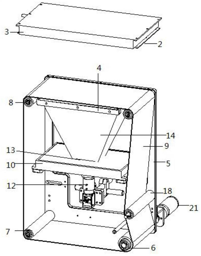
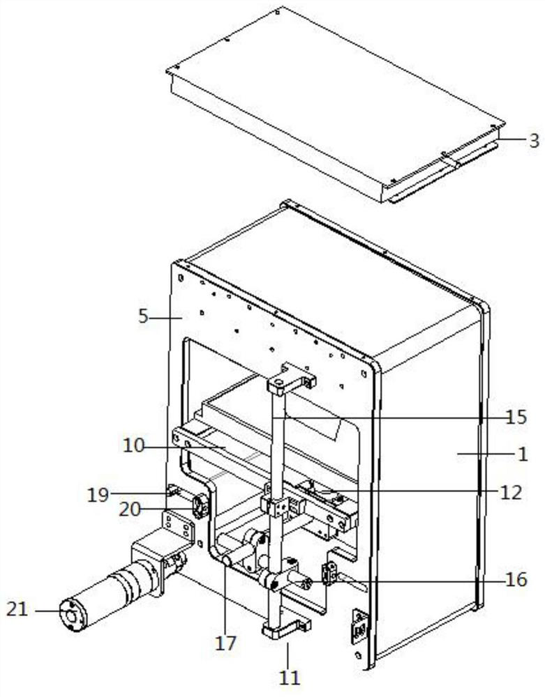
[0026] according to figure 1 and figure 2 The conveying detection mechanism shown includes a frame 1, an upper light source 3 is installed on the top of the frame 1 through an upper fixing bracket 2, a lower visual glass 4 is fixed on the upper inner side of the frame 1, and the front and rear sides of the frame 1 are installed There is a fixed plate 5, the lower visual glass 4 is located below the upper light source 3, the inner bottom side of the frame 1 is provided with a rubber-coated driving roller 6, and the other side of the inner bottom of the frame 1 is provided with a rubber-coated driven roller 7. There are rubber-coated driven rollers I8 on both sides of the inner upper part. The rubber-coated driving roller 6 is connected to the rubber-coated driven roller 7 and the rubber-coated driven roller I8 through a transparent belt 9. The transparent belt 9 passes through the lower visual glass. Above 4, the ends of the rubber-coated driving roller 6, the rubber-coated d...

Embodiment 2

[0028] according to figure 1 and figure 2 The conveying detection mechanism shown includes a frame 1, an upper light source 3 is installed on the top of the frame 1 through an upper fixing bracket 2, a lower visual glass 4 is fixed on the upper inner side of the frame 1, and the front and rear sides of the frame 1 are installed There is a fixed plate 5, the lower visual glass 4 is located below the upper light source 3, the inner bottom side of the frame 1 is provided with a rubber-coated driving roller 6, and the other side of the inner bottom of the frame 1 is provided with a rubber-coated driven roller 7. There are rubber-coated driven rollers I8 on both sides of the inner upper part. The rubber-coated driving roller 6 is connected to the rubber-coated driven roller 7 and the rubber-coated driven roller I8 through a transparent belt 9. The transparent belt 9 passes through the lower visual glass. Above 4, the ends of the rubber-coated driving roller 6, the rubber-coated d...


PUM


Abstract

The invention discloses a conveying detection mechanism which comprises a frame, an upper light source is installed at the top of the frame through an upper fixing support, lower visual glass is fixedto the upper portion of the inner side of the frame, fixing plates are installed on the front side and the rear side of the frame, one side of the bottom of the inner side of the frame is provided with a rubber-coated driving roller, the other side of the bottom of the inner side of the frame is provided with a rubber-coated driven roller, and rubber-coated driven rollers I are arranged on the two sides of the upper portion of the inner side of the frame; the rubber-coated driving roller is connected with the rubber-coated driven roller and the rubber-coated driven rollers I through a transparent belt, the transparent belt passes through the upper portion of the lower visual glass, and the rubber-coated driving roller is connected with a driving motor; and a lower light source is fixed tothe middle of the inner side of the frame and located below the lower visual glass, a camera adjusting rod is installed on a fixing plate on the rear side of the frame, and a camera is installed on the camera adjusting rod and located in the frame. According to the conveying detection mechanism, the transparent belt is adopted, so that the recognition degree of information acquired by the camerain the moving process of medicines is ensured.

Description

technical field [0001] The invention relates to the technical field of delivery detection, in particular to a delivery detection mechanism and a working method. Background technique [0002] Medicine bags and medicine bottles are common medical supplies. They are labeled and distributed to different patients in different departments according to the needs of patients who use them. Currently, hospitals need to manually label and classify them, which is time-consuming and laborious. Contents of the invention [0003] The purpose of the present invention is to solve the time-consuming and labor-intensive problem that traditional Chinese medicine hospitals need manual labeling and classification, and propose a transport detection mechanism and working method. [0004] In order to achieve the above object, the present invention adopts the following technical solutions: a conveying detection mechanism, including a frame, the top of the frame is equipped with an upper light sourc...

Claims


Application Information

Patent Timeline
Patent Type & Authority Applications(China)
IPC IPC(8): B65C9/02B65C9/40B65G15/32B65G23/44G06K9/20G06K9/32H04N5/232
CPCB65C9/02B65C9/40B65G15/32B65G23/44G06V10/147G06V20/62G06V30/10H04N23/695
Inventor 李永国
Owner 上海贝林尔智能系统有限公司
Learn More