Unlock instant, AI-driven research and patent intelligence for your innovation.
Automatic loading and unloading device for chemical liquid
What is Al technical title?
Al technical title is built by PatSnap Al team. It summarizes the technical point description of the patent document.
A technology for automatic loading and unloading of chemical liquids, applied in liquid bottling, liquid treatment, packaging, etc., which can solve problems such as time-consuming and labor-intensive, manual operation, and material leakage
Pending Publication Date: 2021-03-23
马鞍山神剑新材料有限公司
View PDF0 Cites 0 Cited by
Summary
Abstract
Description
Claims
Application Information
AI Technical Summary
This helps you quickly interpret patents by identifying the three key elements:
Problems solved by technology
Method used
Benefits of technology
Problems solved by technology
[0005] Aiming at the above-mentioned deficiencies in the prior art, the present invention provides an automatic chemical liquid loading and unloading device, which is used to solve the problem of loading and unloading chemical liquids in the prior art, which requires manual operation and is time-consuming and laborious. After the materials are unloaded, the pump is connected to the storage tank If there is material in the pipeline of the pump, if the outlet valve of the pump is not closed tightly, internal leakage or aging of the pump seal, the material may leak out from the shaft seal of the pump, etc.
Method used
Image
Click on the blue label to locate the original text in one second.
Reading with bidirectional positioning of images and text.
Examples
Embodiment 1
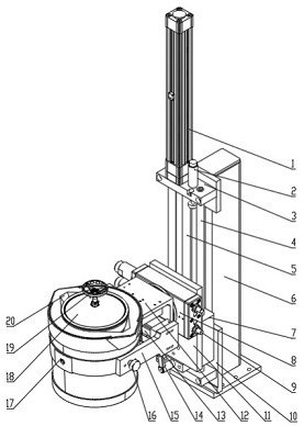
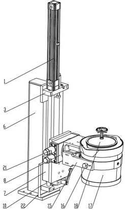
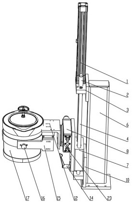
[0022] Such as Figure 1-3 As shown, the chemical liquid automatic loading and unloading device includes a support base 6, a lifting assembly, a rotating assembly, a fixed assembly, a storage tank 17 and an upper cover 18;
[0023] The lifting assembly is provided with the front end of the support seat 6, the rotating assembly is arranged at the front end of the lifting assembly, the fixed assembly is arranged at the front end of the rotating assembly, the storage tank 17 is arranged in the fixed assembly, the upper cover 18 is arranged on the upper end of the storage tank 17, and the lower end of the upper cover 18 is connected to the storage tank. The inner upper end of the tank 17 is detachably connected.
[0024] The rotating assembly includes a connecting shaft 23, a fixed box 8, a rotating motor 21, a threaded rod 9 and a connecting plate 11, the rear end of the fixed box 8 is connected to the front side of the upper end of the connecting plate 11, and the upper and lowe...
Embodiment 2
[0027] Such as Figure 1-3 As shown, the chemical liquid automatic loading and unloading device includes a support base 6, a lifting assembly, a rotating assembly, a fixed assembly, a storage tank 17 and an upper cover 18;
[0028] The lifting assembly is provided with the front end of the support seat 6, the rotating assembly is arranged at the front end of the lifting assembly, the fixed assembly is arranged at the front end of the rotating assembly, the storage tank 17 is arranged in the fixed assembly, the upper cover 18 is arranged on the upper end of the storage tank 17, and the lower end of the upper cover 18 is connected to the storage tank. The inner upper end of the tank 17 is detachably connected.
[0029] The rotating assembly includes a connecting shaft 23, a fixed box 8, a rotating motor 21, a threaded rod 9 and a connecting plate 11, the rear end of the fixed box 8 is connected to the front side of the upper end of the connecting plate 11, and the upper and lowe...
PUM
Abstract
The invention relates to the technical field of chemical industry, in particular to an automatic loading and unloading device for chemical liquid. The automatic loading and unloading device comprisesa supporting seat, a lifting assembly, a rotating assembly, a fixing assembly, a storage tank and an upper cover. The lifting assembly is arranged at the front end of the supporting seat; the rotatingassembly is arranged at the front end of the lifting assembly; the fixing assembly is arranged at the front end of the rotating assembly; the storage tank is arranged in the fixing assembly; and theupper cover is arranged at the upper end of the storage tank. According to the automatic loading and unloading device provided by the invention, the lifting assembly and the rotating assembly are arranged; the lifting assembly controls the height of the storage tank according to the situation, and chemical liquid can be conveniently and exactly conveyed into the storage tank; the rotating assemblycan control the left-right inclination angle of the storage tank according to the situation, and the chemical liquid in the tank can be conveniently and better conveyed to an unloading device; and the automatic loading and unloading device has a relatively high automation degree in overall structure, saves time and efforts, and realizes complete unloading.
Description
technical field [0001] The invention relates to the technical field of chemical industry, in particular to an automatic loading and unloading device for chemical liquid. Background technique [0002] After the chemical liquid is produced, it needs to be stored in a storage tank for later use, and in order to prevent the chemical liquid in the storage tank from changing qualitatively, the storage tank is stored in a specific space and transported when needed . [0003] At present, the commonly used existing technology in the industry to transport chemical liquids from storage tanks is as follows: a discharge area is set outside the storage tank area, and different types of pumps are selected in the area according to the materials to be unloaded. The pipeline is connected to the discharge port of the tank truck. When unloading, the storage tank is connected to the inlet of the pump. Open the inlet and outlet valve of the pump, then open the discharge valve of the tank truck, ...
Claims
Application Information
Patent Timeline
Application Date:The date an application was filed.
Publication Date:The date a patent or application was officially published.
First Publication Date:The earliest publication date of a patent with the same application number.
Issue Date:Publication date of the patent grant document.
PCT Entry Date:The Entry date of PCT National Phase.
Estimated Expiry Date:The statutory expiry date of a patent right according to the Patent Law, and it is the longest term of protection that the patent right can achieve without the termination of the patent right due to other reasons(Term extension factor has been taken into account ).
Invalid Date:Actual expiry date is based on effective date or publication date of legal transaction data of invalid patent.

