Developing roller
A developing roller and surface layer technology, applied in the field of developing rollers, can solve the problems of damaged film formation and toner blocks, image formation and printing quality degradation, excessive increase, etc., to achieve the goal of suppressing excessive increase and reducing toner damage Effect
Pending Publication Date: 2021-03-23
株式会社アーケム
View PDF3 Cites 0 Cited by
- Summary
- Abstract
- Description
- Claims
- Application Information
AI Technical Summary
Problems solved by technology
Due to poor charging of toner, poor adhesion of toner, and melting and sticking of toner, toner damage leads to filming and toner clumping, etc., all of which lead to a decrease in the amount of toner conveyed by the developing roller. Excessive increase, causing problems in image formation and print quality deterioration
Method used
View moreImage
Smart ImageViewing Examples

Examples
Embodiment
[0130] The present disclosure is described in more detail below with reference to Examples, which should not be construed as limiting the scope of the present disclosure.
Login to View More PUM
| Property | Measurement | Unit |
|---|---|---|
| Thickness | aaaaa | aaaaa |
Abstract
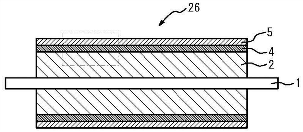
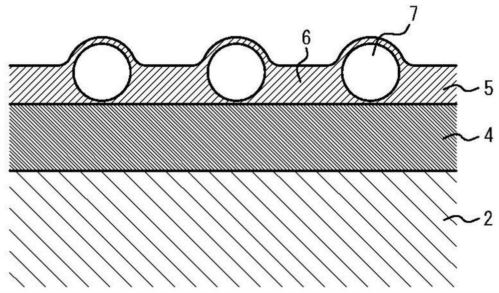
The invention relates to a developing roller. Provided is a developing roller including a shaft, and a base layer and a surface layer sequentially formed in a radial direction on an outer peripheral portion of the shaft, in which 1) a low-resilience layer is provided between the base layer and the surface layer, 2) when measured under conditions of a temperature of 23 DEG C, an amplitude of + / -20[mu] m, and a frequency of 6 Hz, the low-resilience layer is provided between the base layer and the surface layey, wherein the loss tangent tan [delta] value of the low-resilience layer is greater than any one of the loss tangent tan [delta] values of the base layer and the surface layer, and 3) the Asker C hardness / thickness value of the developing roller as defined by the following formula (1)is 500 or less: Asker C hardness / thickness value of the developing roller = Asker C hardness of the developing roller * (thickness of the developing roller + 6) (1).
Description
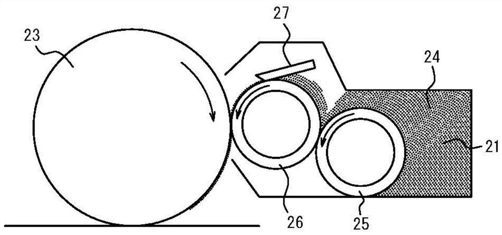
technical field [0001] The present disclosure relates to a developer roller. Background technique [0002] In an image forming apparatus typified by a copier, or a laser beam printer, etc., image formation and printing are performed through the following series of processes, and the series of processes are repeated periodically: [0003] 1) Evenly charge (charge) the surface of the photoreceptor; [0004] 2) The image of the target is read by the optical system, the image information is projected on the photoreceptor as light (exposure), and a latent image is formed by eliminating the charge of the exposed part of the photoreceptor (formation of electrostatic latent image); [0005] 3) Adhering toner to a photoreceptor on which an electrostatic latent image has been formed, and forming a toner image from the electrostatic latent image (development); [0006] 4) Overlaying the toner image on a recording medium such as paper and fixing (transferring and fixing); [0007] 5)...
Claims
Login to View More Application Information
Patent Timeline
 IPC IPC(8): G03G15/08
CPCG03G15/0818G03G15/0808
Inventor 藤泽祐辅山下聪太郎
Owner 株式会社アーケム