
Method and apparatus for controlling an internal combustion engine

a control apparatus and internal combustion engine technology, applied in the direction of electric control, fuel injection control, machines/engines, etc., can solve the problems of low rotation speed, insufficient intake air volume, and low engine rotation speed, so as to reduce the occurrence of large variation in the characteristics of the throttle valve and improve the control of the intake air volume.

Active Publication Date: 2016-08-18
TOYOTA JIDOSHA KK
View PDF1 Cites 0 Cited by
  • Summary
  • Abstract
  • Description
  • Claims
  • Application Information

AI Technical Summary

Benefits of technology

The invention is about a control system for an internal combustion engine that reduces the decline in control of the intake air volume. It achieves this by updating the learning values of the engine based on the opening degrees of the throttle valve at different engine speeds. By doing so, it prevents deviation between the learning values and the characteristic values associated with the opening degrees, which prevents large variation in the throttle valve characteristics and improves control of the intake air volume. Overall, this system maintains the performance of the engine and reduces the likelihood of reducing power output.

Problems solved by technology

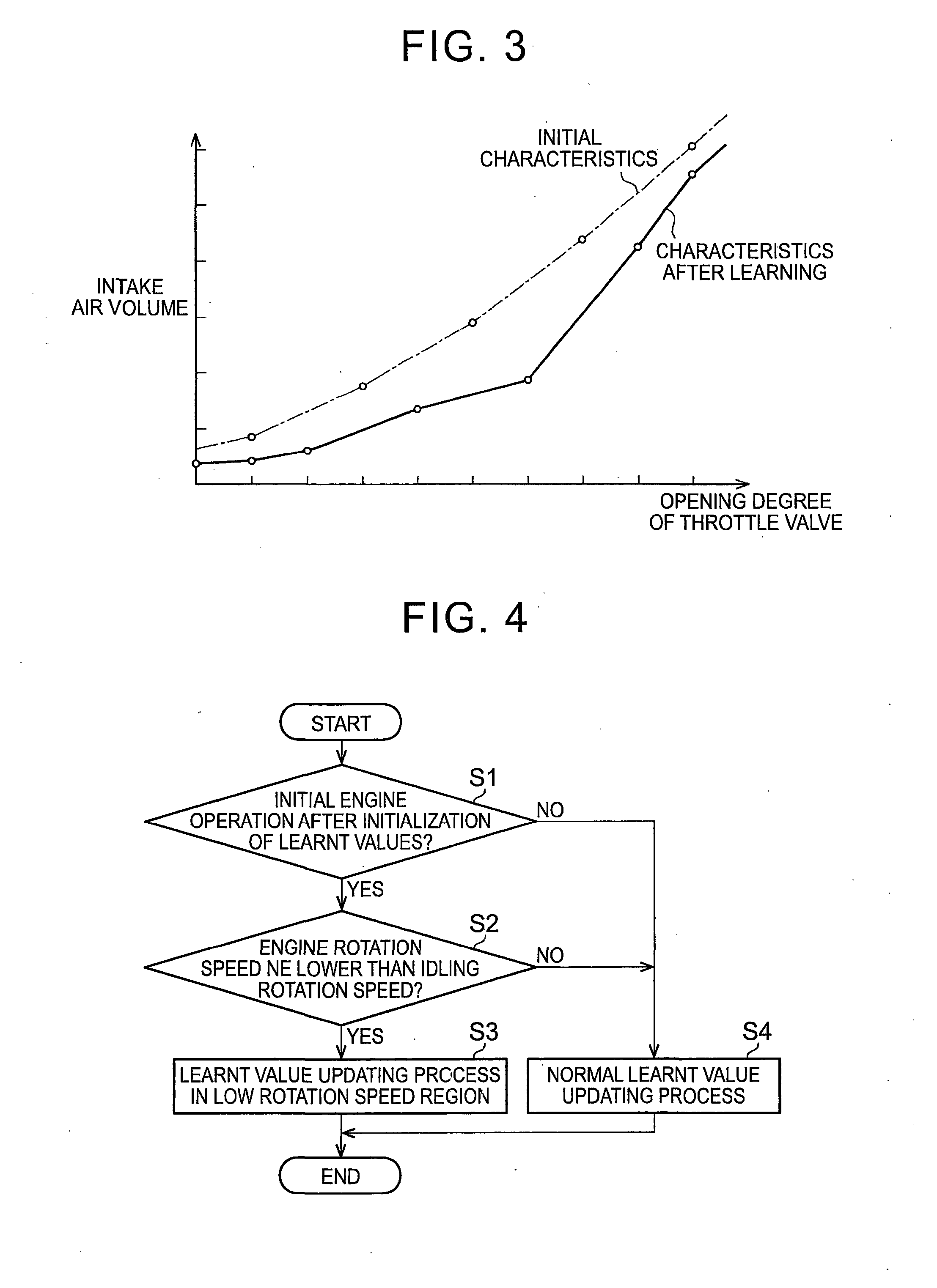
Therefore, when the intake air volume at the same opening degree is reduced, due to the occurrence of temporal change in the throttle valve, then the intake air volume becomes insufficient and the engine rotation speed becomes lower than the idling rotation speed.
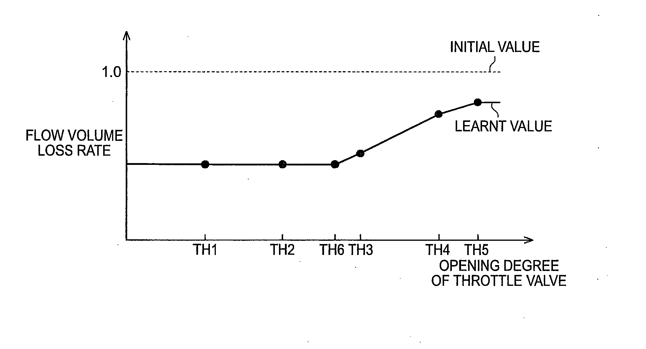
Therefore, when the opening degree of the throttle valve varies between an opening degree region where the learnt value is updated frequently as described above and an opening degree region where the learnt value is not updated, then there is a possibility of an excessively large range of increase / decrease in the intake air amount with the change in the opening degree.
Consequently, there is a possibility of decline in the control of the intake air volume of the internal combustion engine.

Method used


Image

  • Method and apparatus for controlling an internal combustion engine
  • Method and apparatus for controlling an internal combustion engine
  • Method and apparatus for controlling an internal combustion engine

Examples


Embodiment Construction

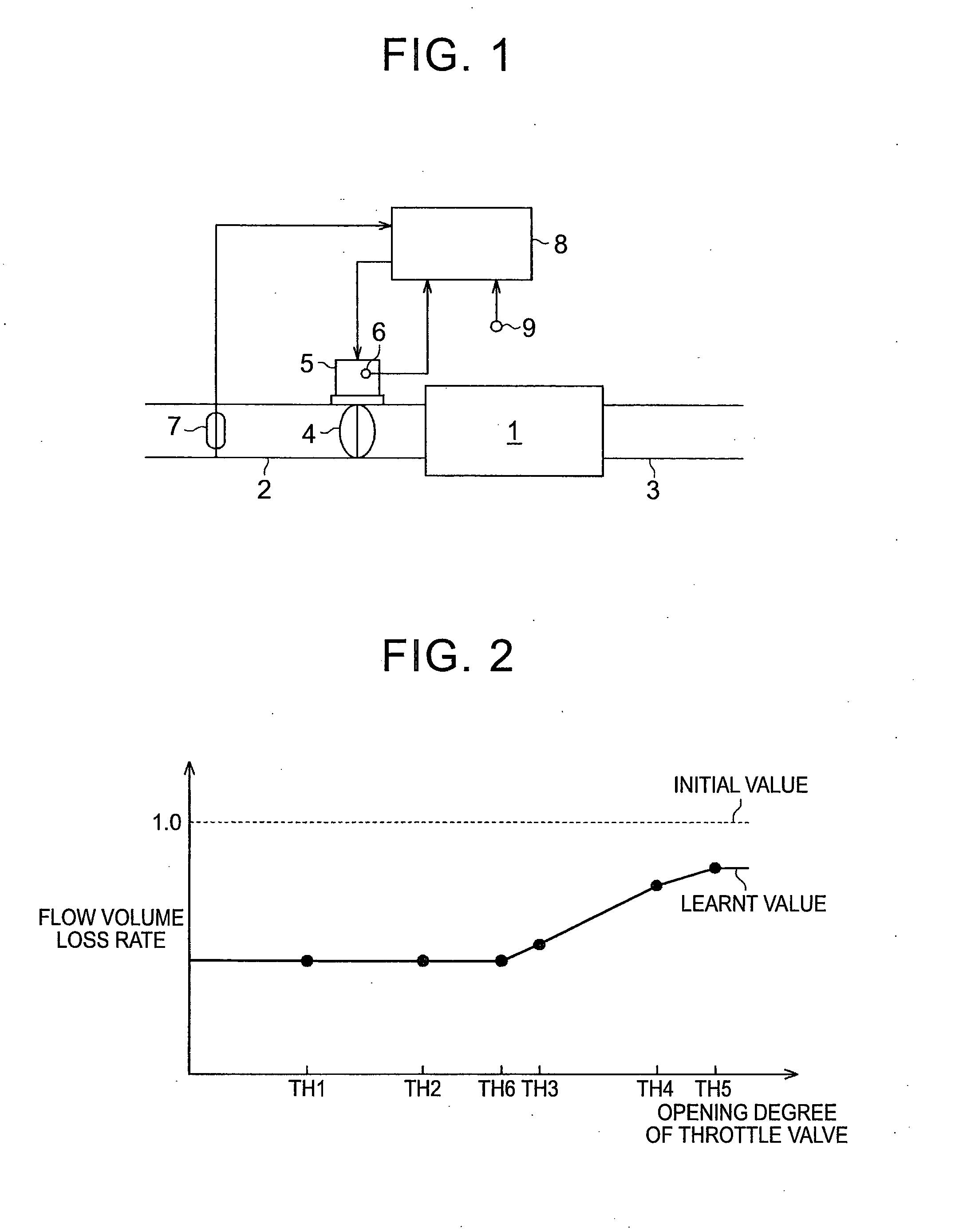
[0030]Below, a first embodiment of a control apparatus for an internal combustion engine is described with reference to FIGS. 1 to 5C.

[0031]As shown in FIG. 1, an air intake passage 2 and an exhaust gas passage 3 are connected respectively to a combustion chamber1 of an internal combustion engine. A throttle valve 4 is provided in the air intake passage 2. The throttle valve 4 adjusts the volume of the intake air which is introduced into the combustion chamber 1 by the opening degree thereof. The throttle valve 4 is driven by the throttle motor 5. The throttle motor 5 has an in-built throttle sensor 6 for detecting the opening degree of the throttle valve 4. An air flow meter 7 for detecting the intake air volume flowing in the air intake passage 2 is disposed in a portion of the air intake passage 2 to the upstream side of the throttle valve 4 in terms of the flow of intake air.

[0032]An electronic control unit 8 which implements overall control of the internal combustion engine is ...


PUM


Abstract

A control apparatus for an engine, the control apparatus includes an ECU. The ECU is configured to: (i) estimate a characteristic value indicating divergence from a reference value of an intake air volume, (ii) store the characteristic value as a learnt value, (iii) calculate the characteristic values for an opening degrees for which learning has not been completed, (iv) learn the characteristics of the throttle valve and reflect the characteristics in control of the intake air volume, (v) update the learnt value at which an engine rotation speed is equal to or greater than an idling rotation speed during an initial engine operation after initialization of the learnt values, (vi) update the learnt value at which an engine rotation speed is lower than an idling rotation speed, by storing a value equal to the learnt value for the smallest opening degree for which learning has already been completed.

Description

BACKGROUND OF THE INVENTION[0001]1. Field of the Invention[0002]This invention relates to a control apparatus and a control method for an internal combustion engine.[0003]2. Description of Related Art[0004]There is a possibility that the characteristics of a throttle valve may vary with temporal change due to, for example, the accumulation of deposits. In other words, even at the same opening degree, the opening area becomes narrower as the accumulation of deposits progresses, and the intake air amount may be reduced.[0005]In the control apparatus for an internal combustion engine described in Japanese Patent Application Publication No. 2012-17679 A (JP 2012-17679 A), the rate of change in the flow volume in each opening degree region which is divided in accordance with the opening degree of the throttle valve is learnt, so as to correspond to such temporal change in the characteristics of the throttle valve. The rate of change in the flow volume is an indicator which represents the...

Claims


Application Information

Patent Timeline
Patent Type & Authority Applications(United States)
IPC IPC(8): F02D41/24F02D41/08F02D41/26F02D41/00
CPCF02D45/00F02D41/2464F02D41/0002F02D41/26F02D41/2438F02D41/2441F02D41/08
Inventor NOZAKI, TOMOHIRO
Owner TOYOTA JIDOSHA KK
Learn More