
Vehicular mirror device

a technology of mirror housing and clutch disk, which is applied in the direction of machine supports, cycle equipment, roofs, etc., can solve the problems of excessive load on the torque transmission mechanism and mirror housing, the coupling cannot be released between the clutch disk and the clutch housing, etc., and achieve the effect of suppressing

Active Publication Date: 2010-12-28
KK TOKAI RIKA DENKI SEISAKUSHO
View PDF5 Cites 13 Cited by
  • Summary
  • Abstract
  • Description
  • Claims
  • Application Information

AI Technical Summary

Benefits of technology

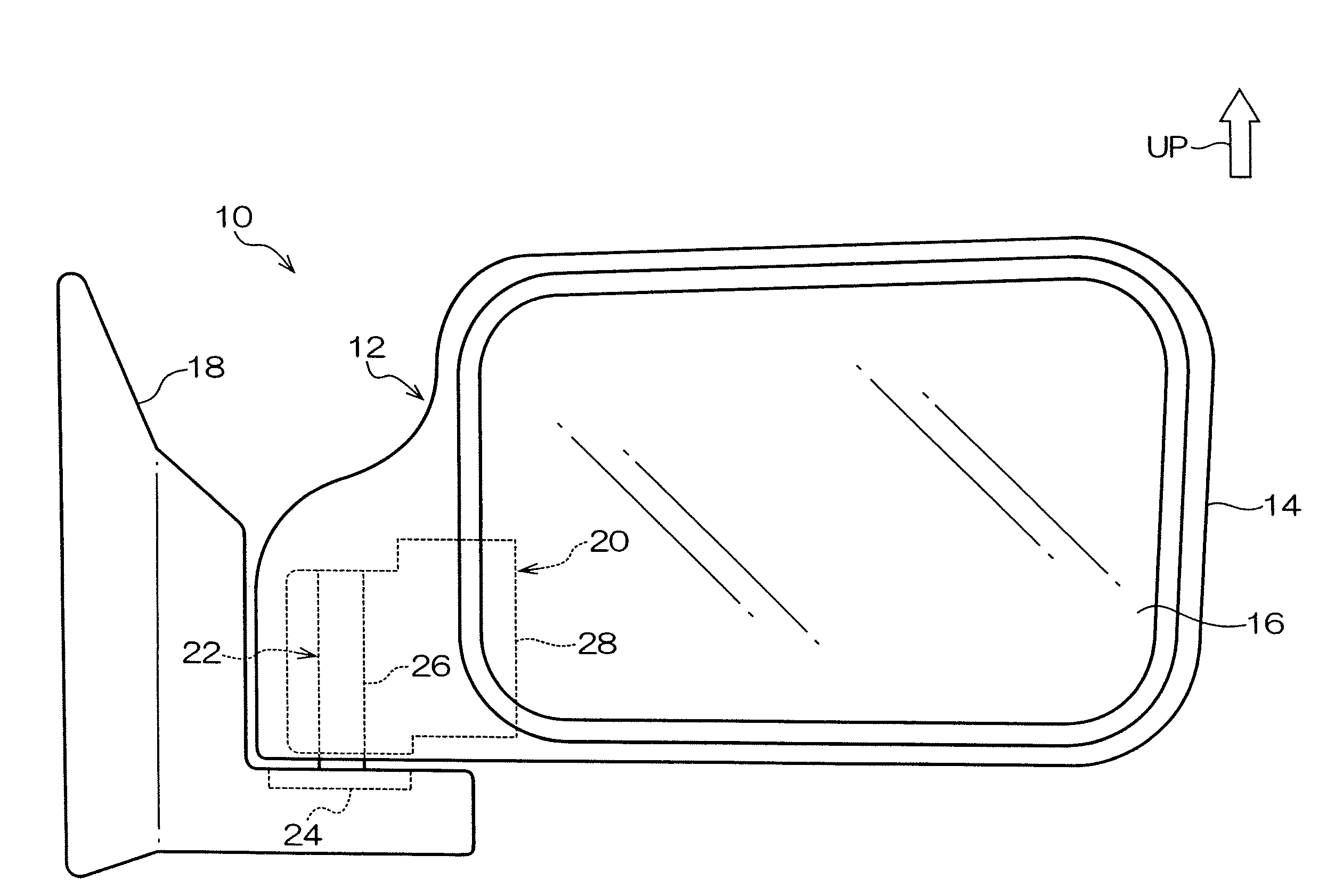
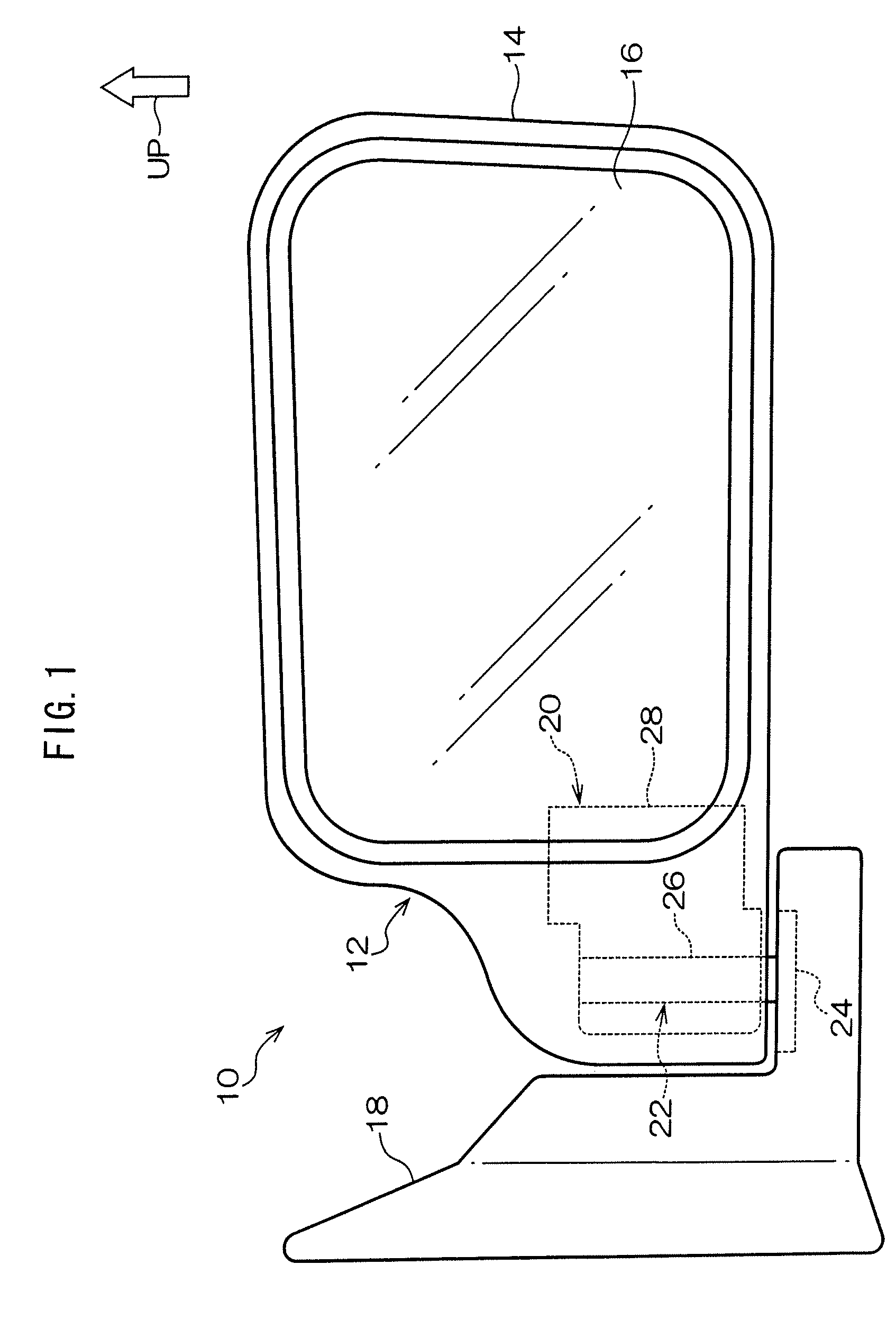
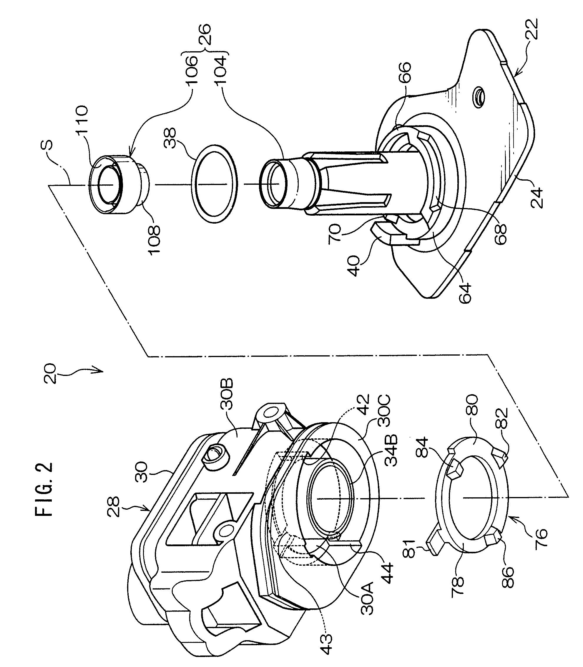
The present invention provides a vehicular mirror device that effectively suppresses the operation torque on the driving clutch disk during the engagement of clutch projections out of clutch grooves, from the start of device assembly. The device includes a driven clutch disk, a clutch biasing member, a clutch groove, and a clutch projection. The clutch groove is formed in a trapezoidal shape, and the clutch projection is formed in a trapezoidal shape with decreasing width from the base to the tip. This allows the clutch projection to move out of the clutch groove when torque exceeds a set value, reducing the contact pressure force and allowing the driven clutch disk to rotate. The technical effect of this invention is to suppress the operation torque on the driving clutch disk during the engagement of clutch projections, improving the performance and efficiency of the vehicular mirror device.

Problems solved by technology

Even when an excessive torque much greater than a previously set threshold is transmitted to the driving clutch disk, there is a possibility that the coupling cannot be released between the clutch disks.
This possibly applies an excessive load to the torque transmission mechanism and mirror housing and causes damages to those.

Method used


Image

  • Vehicular mirror device
  • Vehicular mirror device
  • Vehicular mirror device

Examples


examples

[0102]FIG. 19 shows a relationship between an operation torque and a number of operation cycles of the first clutch assembly in the door mirror devices according to an example of the invention and comparative examples. In the door mirror device according to the present example, the clutch projections and the clutch grooves according to the foregoing present embodiment (see FIGS. 15, 16 and 17) are formed respectively in the clutch disk and the gear plate that constitute the first clutch assembly.

[0103]Meanwhile, in the door mirror device according to comparative example 1, clutch projections and clutch grooves of a clutch disk and a gear plate are in parallel with the radial direction whose center is the axis “S” and, moreover, edge lines L1-L4 (those edge lines have a meaning similarly to that in the foregoing embodiment) are parallel with the centerline of the clutch projections and clutch grooves of the clutch disk and the gear plate.

[0104]In the door mirror device according to c...


PUM


Abstract

The operation torque during disengaging of clutch projections out of clutch grooves, is effectively suppressed from excessively increasing immediately after start of device assembling. In a door mirror device, a gear plate has clutch grooves made substantially in trapezoidal form, in circumferential cross-section, increasing in width from a groove bottom to an opening end. A clutch disk has clutch projections made substantially in trapezoidal form, in circumferential cross-section, decreasing in width in taper form from a base toward a tip wherein the top surfaces are made in an inverted radial form decreasing in width from inner periphery to outer periphery. Due to this, when a torque exceeding a set value is transmitted to the gear plate, the pressure-contact area of the clutch projection with the clutch groove gradually moves from inner periphery to outer periphery while moving the clutch disk upward against a bias force of a clutch spring.

Description

CROSS-REFERENCE TO RELATED APPLICATION[0001]This application claims priority under 35 USC 119 from Japanese Patent Application No. 2006-347855, the disclosure of which is incorporated by reference herein.BACKGROUND[0002]1. Field of the Invention[0003]The present invention relates to a vehicular mirror device for use as an automotive door mirror device or the like and to couple a rearview mirror to a vehicle body and rotatably support it on the vehicle body.[0004]2. Related Art[0005]There is known, for example, a description in Japanese Utility Model Registration No. 2,548,021 as a power-operated vehicular door mirror device. The vehicular mirror device described in Japanese Utility Model Registration No. 2,548,021 (hereinafter, referred merely to as a “door mirror device”) has a mirror base on which a cylindrical support shaft is provided upright, a mirror housing rotatably supported on the support shaft, a torque transmission mechanism that conveys the torque generated at a drive t...

Claims


Application Information

Patent Timeline
Patent Type & Authority Patents(United States)
IPC IPC(8): A47G1/24B60R1/02
CPCB60R1/074
Inventor YOSHIDA, SHIGEKITSUJIUCHI, YOSHIO
Owner KK TOKAI RIKA DENKI SEISAKUSHO
Learn More