
Switching control device and method and power supply system

A technology for controlling devices and power supply parameters, which is applied to circuit devices, electrical components, emergency power supply arrangements, etc., and can solve problems such as load damage, instantaneous sudden change in switching time intervals, etc.

Pending Publication Date: 2021-03-23
SHENZHEN POWER SUPPLY BUREAU
View PDF7 Cites 0 Cited by
  • Summary
  • Abstract
  • Description
  • Claims
  • Application Information

AI Technical Summary

Problems solved by technology

[0003] In the traditional technology, the bypass power supply and the uninterruptible power supply are switched in the way of mutual backup and mutual switching. However, such a switching method will cause switching disconnection time intervals and instantaneous sudden changes, which will cause damage to the load.

Method used


Image

  • Switching control device and method and power supply system
  • Switching control device and method and power supply system
  • Switching control device and method and power supply system

Examples


Embodiment Construction

[0048] In order to make the above objects, features and advantages of the present invention more comprehensible, specific implementations of the present invention will be described in detail below in conjunction with the accompanying drawings. In the following description, numerous specific details are set forth in order to provide a thorough understanding of the present invention. However, the present invention can be implemented in many other ways different from those described here, and those skilled in the art can make similar improvements without departing from the connotation of the present invention, so the present invention is not limited by the specific embodiments disclosed below.

[0049] The serial numbers assigned to components in this document, such as "first", "second", etc., are only used to distinguish the described objects, and do not have any sequence or technical meaning. The "connection" and "connection" mentioned in this application all include direct and...


PUM


Abstract

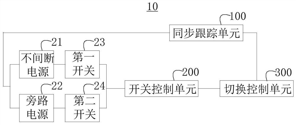
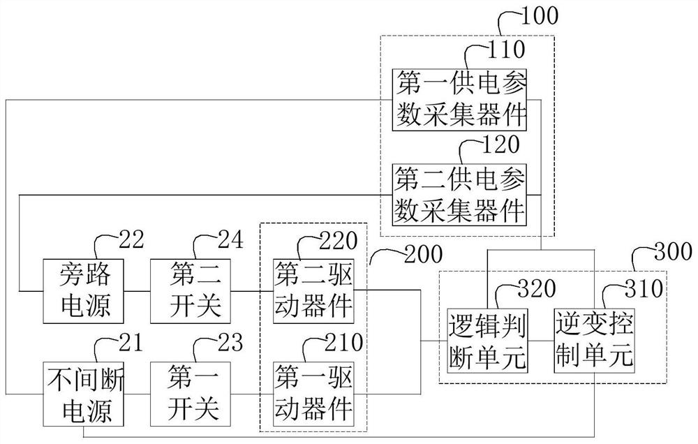
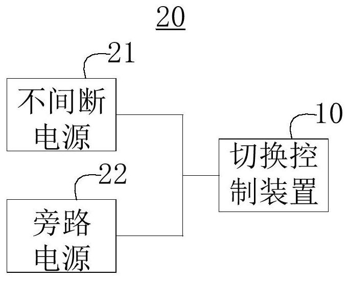
The invention relates to a switching control device and method and a power supply system. The switching control device comprises a synchronous tracking unit, a switch control unit and a switching control unit. The synchronous tracking unit is used for synchronously acquiring a first power supply parameter of an uninterruptible power supply and a second power supply parameter of a bypass power supply; the switching control unit is used for adjusting the uninterruptible power supply according to the second power supply parameter so as to synchronize the first power supply parameter with the second power supply parameter; the switching control unit is also used for judging whether a switching control device meets a switching condition or not according to the working state of the uninterruptible power supply, the working state of the bypass power supply, the first power supply parameter and the second power supply parameter; and if so, the on-off states of a first switch and a second switch are controlled at the same time through the switching control unit, so that switching between the uninterruptible power supply and the bypass power supply is realized. When the switching control device provided by the invention is used for switching control, an open-circuit time interval and an instantaneous break variable can be avoided, so that damage to a load can be avoided.

Description

technical field [0001] The invention relates to the technical field of power supply control, in particular to a switching control device, method and power supply system. Background technique [0002] With the continuous advancement of information technology and the rapid development of the national economy, more and more departments have put forward higher and higher requirements for power quality. Uninterruptible power supplies are widely used due to their advantages of parallel connection expansion and convenient maintenance. . In actual use, when the bypass power supply fails, it can be switched to the uninterruptible power supply to continue supplying power to ensure the normal operation of the load. [0003] In the traditional technology, the bypass power supply and the uninterruptible power supply are switched by means of mutual backup and mutual switching. However, such a switching method will cause switching disconnection time intervals and instantaneous sudden chan...

Claims


Application Information

Patent Timeline
IPC IPC(8): H02J9/06
CPCH02J9/06
Inventor 杨忠亮岑凯辛彭岳云
Owner SHENZHEN POWER SUPPLY BUREAU
Learn More