
Collision detection method of live working robot and live working robot

A live work and collision detection technology, applied in the field of robotics, can solve the problems of inability to cope with environmental changes, low efficiency, noise and delay, and achieve the effect of reducing the number of manual interventions, preventing damage, and avoiding abnormal suspension.

Active Publication Date: 2021-05-14
国网瑞嘉(天津)智能机器人有限公司
View PDF10 Cites 0 Cited by
  • Summary
  • Abstract
  • Description
  • Claims
  • Application Information

AI Technical Summary

Problems solved by technology

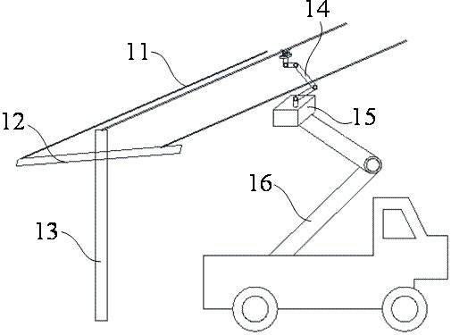
Due to the variety and complexity of the actual on-site operating environment, line layout, cross-arm arrangement, etc., live working robots will inevitably collide with cables, cross-arms and other facilities and equipment during the operation process.
This kind of collision may cause damage to the robot body, and in severe cases, it will damage the transmission line and endanger the safety of the power grid.
At the same time, it is noted that the end effectors of live working robots are generally large in size, complex in structure and rich in functions. After the robot collides with the environment or itself, it will generally switch to the protective stop state (or other similar states) immediately, and the operation will also be stopped. Therefore, it is suspended and needs to be manually reset by the ground operator. This type of operation is generally difficult to implement accurately, and the efficiency is very low, which seriously restricts the automation and intelligence level of live working robots.
[0004] In the prior art, some collision detection technologies for live working robots have been proposed, but among these detection technologies, there are collisions with a small application range and difficulty in detecting small operating targets (for example, the technology using depth vision), and the impact on robots. The detection is not comprehensive enough (for example, the contact collision of the non-terminal part cannot be effectively detected), it cannot cope with environmental changes, and there are misoperations (for example, radar point cloud technology is used, and the operation path planning carried out by radar point cloud technology also makes the operation area limited. )The problem
[0005] In addition, some collision detection technologies also involve the use of six-dimensional force sensors for collision detection. However, in such methods, the manipulator itself and the end effector are usually considered as one, so they cannot deal with the relationship between the manipulator itself and the end effector. In case of collision, especially in a narrow working environment where the scale of the end effector is large and irregular, it is easy to cause damage to the end effector; because the base force sensor is used for the collision detection of the whole arm, the collision force threshold is generally set slightly larger. The micro-collision of the end far away from the base cannot be accurately judged, nor can the precise and high-efficiency force control of the end be realized.
[0006] In some sensorless detection technologies, the joint torque is obtained by using the current of each joint, and then the collision situation is calculated, but this method has the problem of inaccurate detection mentioned above, because it cannot obtain the joint reducer more accurately. Viscous friction and Coulomb friction, and the acceleration is obtained by differentiating the fluctuating speed, artificially introducing noise and time delay

Method used


Image

  • Collision detection method of live working robot and live working robot
  • Collision detection method of live working robot and live working robot
  • Collision detection method of live working robot and live working robot

Examples


Embodiment Construction

[0042] The technical solutions of the present application will be clearly and completely described below in conjunction with the accompanying drawings. Apparently, the described embodiments are some of the embodiments of the present application, not all of them. Based on the embodiments in this application, all other embodiments obtained by persons of ordinary skill in the art without making creative efforts belong to the scope of protection of this application.

[0043] In the description of this application, it should be noted that the terms "center", "upper", "lower", "left", "right", "vertical", "horizontal", "inner", "outer" etc. The indicated orientation or positional relationship is based on the orientation or positional relationship shown in the drawings, and is only for the convenience of describing the present application and simplifying the description, rather than indicating or implying that the referred device or element must have a specific orientation, use a spec...


PUM


Abstract

The present application provides a collision detection method of a live working robot and a live working robot, which relate to the field of robotics and include an acquisition step: using the six-dimensional force sensor on the wrist and the six-dimensional force sensor on the base to obtain the six-dimensional force data of their respective positions; Solution step: establish the DH coordinate system and dynamic equation of the manipulator, and use six-dimensional force data to calculate the collision force solution; judgment step: establish the gravity compensation model of the actuator and set the collision force threshold to judge the collision situation of the live working robot. Effectively monitor the collision of any part of the robot arm and the actuator, before triggering the protective stop of the live working robot itself, to prevent damage to environmental objects and the robot body to the greatest extent, avoid abnormal termination of the operation program, and reduce the number of manual interventions. The actuator and the robot arm body are independently judged for collision, which not only detects the collision of the robot's entire arm, but also satisfies the fine control level of the actuator.

Description

technical field [0001] The present application relates to the field of robots, in particular to a collision detection method of a live working robot and a live working robot. Background technique [0002] As the requirements for the stable operation of urban distribution networks are getting higher and higher, the demand for live work is increasing, but objective conditions such as high labor intensity, high safety risks for high-altitude work, and complex live work environments limit its extensive development. The development and application of live working robots have greatly improved the conditions of live working, reduced the requirements for operators, avoided direct access to live objects, and significantly improved the safety and comfort of work. [0003] In the prior art, live working robots for distribution networks such as 10kV distribution networks mainly use a combination of multi-degree-of-freedom manipulators and special end effectors to perform certain live wo...

Claims


Application Information

Patent Timeline
Patent Type & Authority Patents(China)
IPC IPC(8): B25J5/00B25J19/00B25J9/16H02G1/02
CPCB25J5/007B25J9/1674B25J19/0095H02G1/02
Inventor 李帅李惠宇王新建吕鹏王朝松梁保秋冯俐任青亭李威林德政田鹏云肖雁起罗志竞周文涛王汝新刘明朗冬旭孟希军
Owner 国网瑞嘉(天津)智能机器人有限公司
Learn More