Automatic boxing device for toy sand
An automatic cartoning and sanding technology, which is applied in the directions of packaging, transportation and packaging, and the type of packaging items, can solve the problems of inaccurate control of quantity, time-consuming and labor-intensive, etc., and achieve the effect of reducing operation steps and labor intensity.
- Summary
- Abstract
- Description
- Claims
- Application Information
AI Technical Summary
Problems solved by technology
Method used
Image
Examples
Embodiment 1
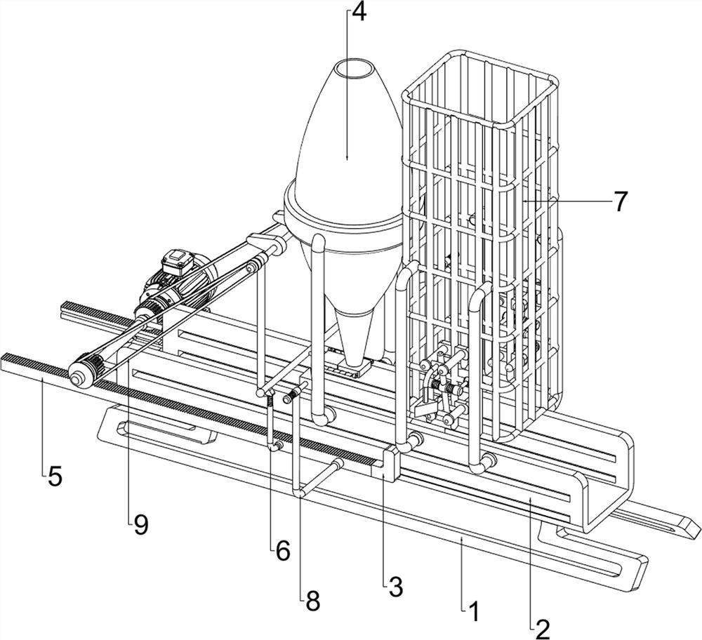
[0062] A kind of toy sand automatic packing device, such as figure 1 As shown, it includes a support foot 1, an installation frame 2, a push plate 3, a feeding mechanism 4 and a moving mechanism 5. The top of the support foot 1 is provided with an installation frame 2, and the inside of the installation frame 2 is slidingly provided with a push plate 3. The upper part of the installation frame 2 A discharge mechanism 4 is arranged in the middle, and a moving mechanism 5 is arranged on the left side of the installation frame 2, and the moving mechanism 5 is connected with the push plate 3.
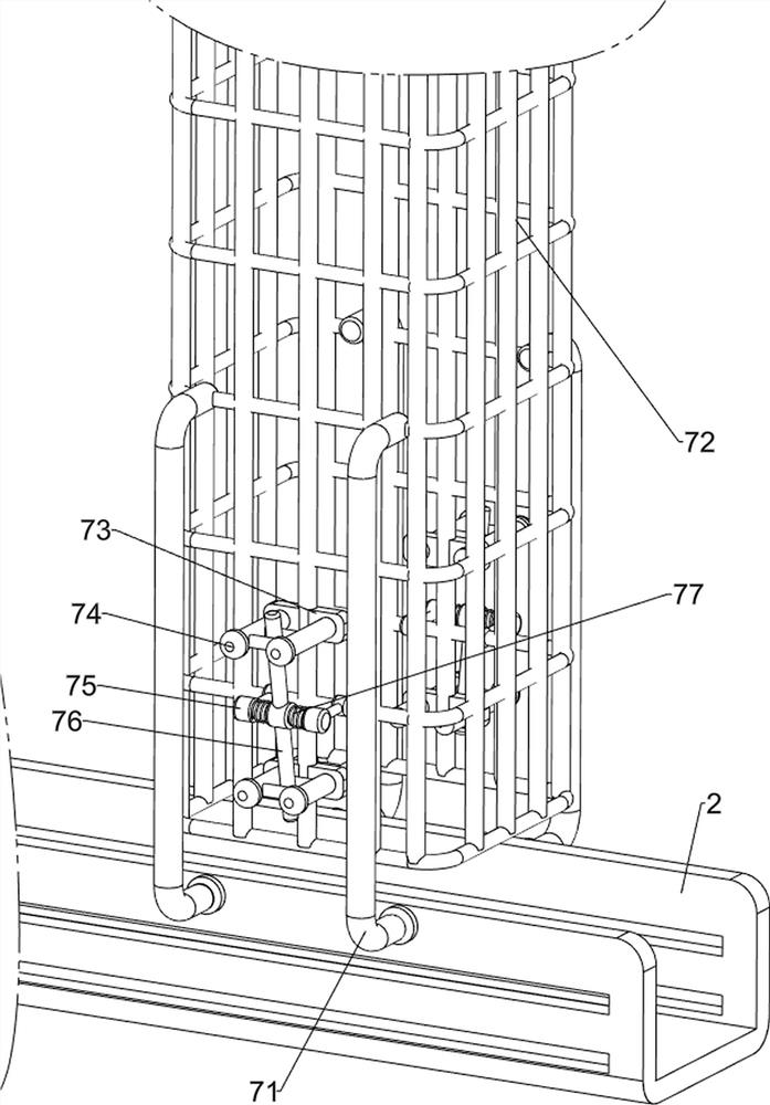
[0063] People can use the present invention to put toy sand into the container. First, the operator puts the toy sand into the discharge mechanism 4, and then the operator places the containers containing the toy sand in the installation frame 2 one by one, and then the operator starts to move Mechanism 5, the moving mechanism 5 will make the push plate 3 push the container to the lower par...
Embodiment 2
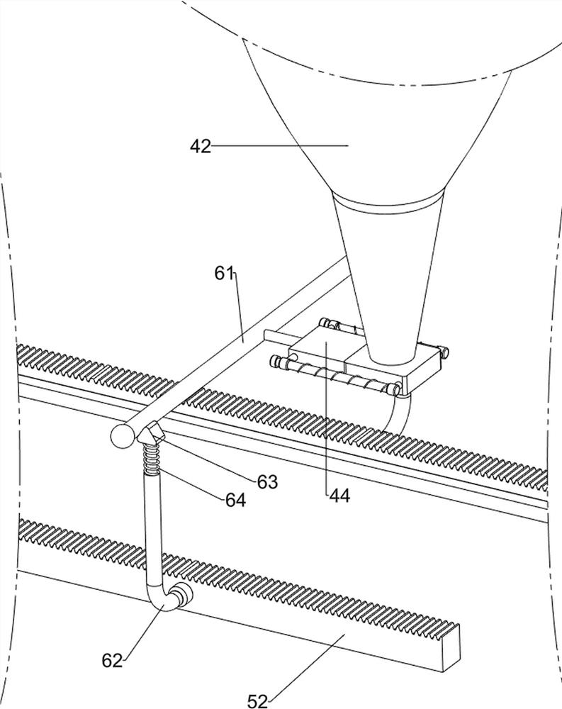
[0065] On the basis of Example 1, such as figure 2 and image 3 As shown, the discharge mechanism 4 includes a discharge frame 42, a first support 41, a hollow plate 43, a slide plate 44, a slide bar 45 and a first spring 46, and the middle of the upper part of the installation frame 2 is provided with a first support 41, the first support 41 is provided with a discharge frame 42, the bottom of the discharge frame 42 is provided with a hollow plate 43, the front and rear sides of the hollow plate 43 are provided with slide bars 45, the inside of the hollow plate 43 is slidingly provided with a slide plate 44, the slide plate 44 and the slide bar 45 Sliding connection, first springs 46 are connected between the left and right sides of the slide plate 44 and the left and right sides of the hollow plate 43, and the first springs 46 are sleeved on the slide bars 45 on the left and right sides.
[0066]The discharge mechanism 4 is used to hold toy sand. The operator pours the toy...
Embodiment 3
[0070] On the basis of Example 2, such as Figure 4 , Figure 5 , Figure 6 and Figure 7 As shown, a push mechanism 6 is also included, and the push mechanism 6 includes a connecting rod 61, a hollow rod 62, a first wedge block 63 and a second spring assembly 64, the left side of the slide plate 44 is provided with a connecting rod 61, and two front and rear racks Hollow rods 62 are arranged in the middle of 52, and second spring assemblies 64 are arranged on the tops of the hollow rods 62, and first wedge blocks 63 are arranged on the tops of the second spring assemblies 64.
[0071] The pushing mechanism 6 can drive the sliding plate 44 to move intermittently. When the container is located at the opening at the bottom of the discharge frame 42, the rack 52 moves to the left, which will drive the hollow rod 62 and the first wedge 63 to move to the left, thereby driving The connecting rod 61 moves to the left, and the moving of the connecting rod 61 to the left drives the ...
PUM
 Abstract
Description
Claims
Application Information
 - R&D
- Intellectual Property
- Life Sciences
- Materials
- Tech Scout
- Unparalleled Data Quality
- Higher Quality Content
- 60% Fewer Hallucinations
Browse by: Latest US Patents, China's latest patents, Technical Efficacy Thesaurus, Application Domain, Technology Topic, Popular Technical Reports.
© 2025 PatSnap. All rights reserved.Legal|Privacy policy|Modern Slavery Act Transparency Statement|Sitemap|About US| Contact US: help@patsnap.com


